《WebGL权威编程指南》书本例题及学习笔记(7~9章)

- 书名:WebGL Programming Guide
- 语言:English
- 作者:Kouichi Matsuda、Rodger Lea
- 版本:1th Edition
- OS: Mac Catalina 10.15.4
- Hardware: Intel Core i9/16G 2667MHz DDR4
- 编译器版本:vscode
- 浏览器:Chrome
Chapter 7 走向3D世界
指定观察方向
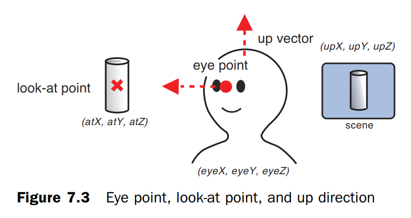
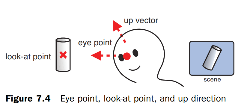
视点、注视点和向上方向
视点、注视点、向上方向示意图,当向上方向变化时,观察到的物体也发生角度变化:
观察3个三角形示例程序
1. 在顶点着色器中定义u_ViewMatrix观察矩阵,然后将其乘入gl_Position
// LookAtTriangles.js
// Vertex shader program
var VSHADER_SOURCE =
    'attribute vec4 a_Position;\n' +
    'attribute vec4 a_Color;\n' +
    'uniform mat4 u_ViewMatrix;\n' +
    'varying vec4 v_Color;\n' +
    'void main() {\n' +
    '   gl_Position = u_ViewMatrix * a_Position;\n' +
    '   v_Color = a_Color;\n' +
    '}\n';
2. 设置视点、注视点、向上方向:
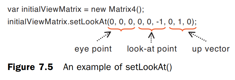
    // Set the eye point, look-at point, and up direction
    var viewMatrix = new Matrix4();
    viewMatrix.setLookAt(0.20, 0.25, 0.25, 0, 0, 0, 0, 1, 0);
注意参数的关系
3. 将视点矩阵传入到顶点着色器
    // Get the storage location of u_ViewMatrix variable
    var u_ViewMatrix = gl.getUniformLocation(gl.program, 'u_ViewMatrix');

    // Pass the view matrix to u_ViewMatrix variable
    gl.uniformMatrix4fv(u_ViewMatrix, false, viewMatrix.elements);
程序代码:
// LookAtTriangles.js // Vertex shader program var VSHADER_SOURCE = 'attribute vec4 a_Position;\n' + 'attribute vec4 a_Color;\n' + 'uniform mat4 u_ViewMatrix;\n' + 'varying vec4 v_Color;\n' + 'void main() {\n' + ' gl_Position = u_ViewMatrix * a_Position;\n' + ' v_Color = a_Color;\n' + '}\n'; // Fragment shader program var FSHADER_SOURCE = '#ifdef GL_ES\n' + 'precision mediump float;\n' + '#endif\n' + 'varying vec4 v_Color;\n' + 'void main() {\n' + ' gl_FragColor = v_Color;\n' + '}\n'; function main() { // Retrieve element var canvas = document.getElementById('webgl'); // Get the rendering context for WebGL var gl = getWebGLContext(canvas); if (!gl) { console.log('Failed to get the rendering context for WebGL'); return; } // Initialize shaders if (!initShaders(gl, VSHADER_SOURCE, FSHADER_SOURCE)) { console.log('Failed to initialize shaders.'); return; } // Set the vertex coordinates and color (blue triangle is in front) var n = initVertexBuffers(gl); if (n运行结果:
从指定位置查看旋转三角形
现在要实现旋转的三角形加视点的情形,在顶点着色器中,对gl_Position的赋值关系如下:
方程7.1
gl_Position = * *
本例在LookAtTriangles.js上修改
1. 修改了了顶点着色器,定义了一个uniform mat4类型的模型矩阵,然后按方程7.1计算式计算gl_Position:
// LookAtRotatedTriangles.js // Vertex shader program var VSHADER_SOURCE = 'attribute vec4 a_Position;\n' + 'attribute vec4 a_Color;\n' + 'uniform mat4 u_ViewMatrix;\n' + 'uniform mat4 u_ModelMatrix;\n' + 'varying vec4 v_Color;\n' + 'void main() {\n' + ' gl_Position = u_ViewMatrix * u_ModelMatrix * a_Position;\n' + ' v_Color = a_Color;\n' + '}\n';2. 在main函数中,关联顶点着色器中的模型矩阵:
var u_ModelMatrix = gl.getUniformLocation(gl.program, 'u_ModelMatrix');
3. 将模型矩阵顺时针旋转10度,绕z轴:
// Calculate the rotation matrix var modelMatrix = new Matrix4(); modelMatrix.setRotate(-10.0, 0, 0, 1); // Rotate around z-axis4. 最后将模型矩阵传递进顶点着色器:
gl.uniformMatrix4fv(u_ModelMatrix, false, modelMatrix.elements);
完整的示例程序:
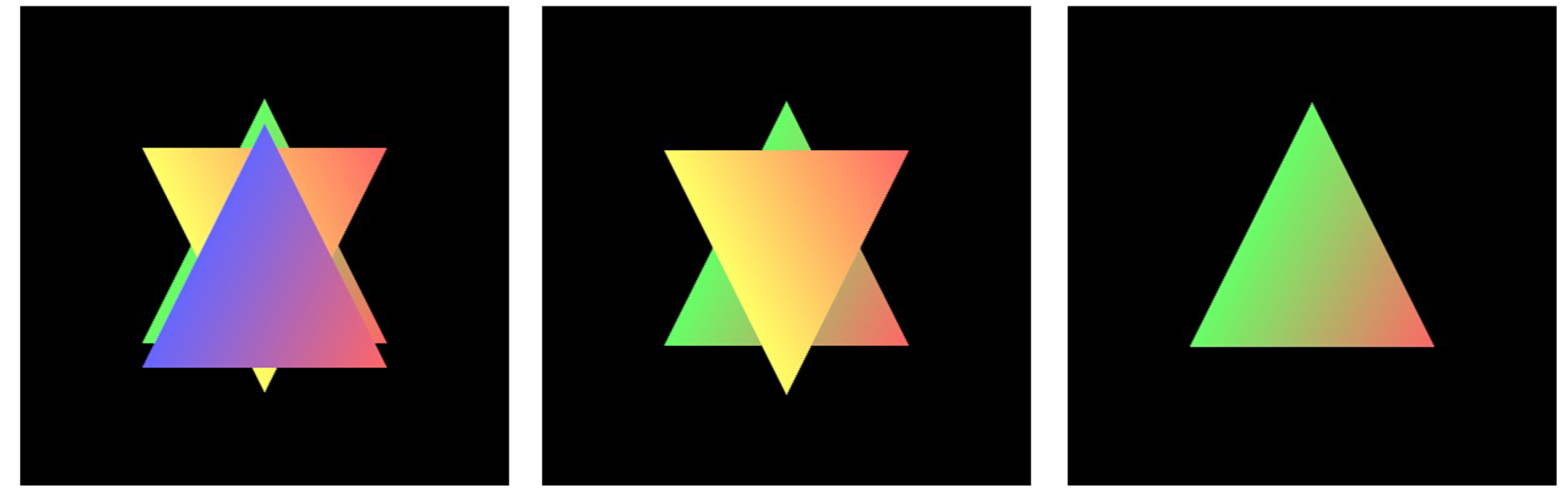
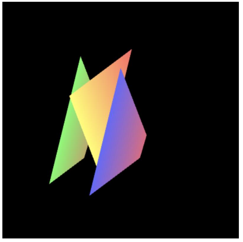
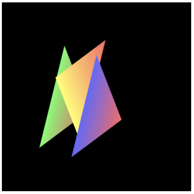
// LookAtRotatedTriangles.js // Vertex shader program var VSHADER_SOURCE = 'attribute vec4 a_Position;\n' + 'attribute vec4 a_Color;\n' + 'uniform mat4 u_ViewMatrix;\n' + 'uniform mat4 u_ModelMatrix;\n' + 'varying vec4 v_Color;\n' + 'void main() {\n' + ' gl_Position = u_ViewMatrix * u_ModelMatrix * a_Position;\n' + ' v_Color = a_Color;\n' + '}\n'; // Fragment shader program var FSHADER_SOURCE = '#ifdef GL_ES\n' + 'precision mediump float;\n' + '#endif\n' + 'varying vec4 v_Color;\n' + 'void main() {\n' + ' gl_FragColor = v_Color;\n' + '}\n'; function main() { // Retrieve element var canvas = document.getElementById('webgl'); // Get the rendering context for WebGL var gl = getWebGLContext(canvas); if (!gl) { console.log('Failed to get the rendering context for WebGL'); return; } // Initialize shaders if (!initShaders(gl, VSHADER_SOURCE, FSHADER_SOURCE)) { console.log('Failed to initialize shaders.'); return; } // Set the vertex coordinates and color (blue triangle is in front) var n = initVertexBuffers(gl); if (n运行结果:左侧为LookAtTriangles.js(未旋转),右侧为LookAtRotatedTriangles.js(z轴顺时针旋转10度),可以看到3个三角形整体绕z轴顺时针旋转了10度

使用模型试图矩阵改善效率
定义:
= *
则,方程7.1可改写为方程7.2:
方程7.2
gl_Position = *
示例程序:
与LookAtRotatedTriangles.js不同的地方
1. 顶点着色器使用模型视图矩阵来代替模型矩阵和视图矩阵:
// LookAtRotatedTriangles_mvMatrix.js // Vertex shader program var VSHADER_SOURCE = 'attribute vec4 a_Position;\n' + 'attribute vec4 a_Color;\n' + 'uniform mat4 u_ModelViewMatrix;\n' + 'varying vec4 v_Color;\n' + 'void main() {\n' + ' gl_Position = u_ModelViewMatrix * a_Position;\n' + ' v_Color = a_Color;\n' + '}\n';2. 在main函数中,不再创建模型矩阵,视图矩阵然后相乘,而是创建模型视图矩阵一起执行完毕,如下:
var modelViewMatrix = new Matrix4(); modelViewMatrix.setLookAt(0.20, 0.25, 0.25, 0, 0, 0, 0, 1, 0).rotate(-10.0, 0, 0, 1);3. 最后将模型视图矩阵传递给顶点着色器:
// Get the storage location of u_ModelViewMatrix var u_ModelViewMatrix = gl.getUniformLocation(gl.program, 'u_ModelViewMatrix'); // Pass the model viewmatrix to u_ModelViewMatrix gl.uniformMatrix4fv(u_ModelViewMatrix, false, modelViewMatrix.elements);完整程序:
// LookAtRotatedTriangles_mvMatrix.js // Vertex shader program var VSHADER_SOURCE = 'attribute vec4 a_Position;\n' + 'attribute vec4 a_Color;\n' + 'uniform mat4 u_ModelViewMatrix;\n' + 'varying vec4 v_Color;\n' + 'void main() {\n' + ' gl_Position = u_ModelViewMatrix * a_Position;\n' + ' v_Color = a_Color;\n' + '}\n'; // Fragment shader program var FSHADER_SOURCE = '#ifdef GL_ES\n' + 'precision mediump float;\n' + '#endif\n' + 'varying vec4 v_Color;\n' + 'void main() {\n' + ' gl_FragColor = v_Color;\n' + '}\n'; function main() { // Retrieve element var canvas = document.getElementById('webgl'); // Get the rendering context for WebGL var gl = getWebGLContext(canvas); if (!gl) { console.log('Failed to get the rendering context for WebGL'); return; } // Initialize shaders if (!initShaders(gl, VSHADER_SOURCE, FSHADER_SOURCE)) { console.log('Failed to initialize shaders.'); return; } // Set the vertex coordinates and color (blue triangle is in front) var n = initVertexBuffers(gl); if (n运行结果截图,与LookAtRotatedTriangles.js相同:
使用按键改变视点
设置按下左键视点+0.10,按下邮件视点+0.10,由于注视点始终是(0,0,0),所以在操作时,视点围绕原点旋转
与示例程序LookAtTriangles.js的不同点:
1. 在main函数中,定义了按键事件:
// Register the event handler to be called on key press document.onkeydown = function(ev) { keydown(ev, gl, n, u_ModelViewMatrix, modelViewMatrix); };2. 按钮传递事件、gl、顶点数、模型视图变量,模型视图矩阵。并定义视点的初始坐标,按下右键,视点x坐标右移,按下左键视点x坐标左移。随后绘制图像。
var g_eyeX = 0.20, g_eyeY = 0.25, g_eyeZ = 0.25; // The eye point function keydown(ev, gl, n, u_ViewMatrix, viewMatrix) { if(ev.keyCode == 39) { // The right arrow key was pressed g_eyeX += 0.10; } else if (ev.keyCode == 37) { // The left arrow key was pressed g_eyeX -= 0.10; } else { return; } // Prevent unnecessary drawing draw(gl, n, u_ViewMatrix, viewMatrix); }3. 在main函数的绘制部分单独调用draw函数来实现绘制。
function draw(gl, n, u_ViewMatrix, viewMatrix) { // Set the eye point and line of sight viewMatrix.setLookAt(g_eyeX, g_eyeY, g_eyeZ, 0, 0, 0, 0, 1, 0); // Pass the model viewmatrix to u_ModelViewMatrix gl.uniformMatrix4fv(u_ViewMatrix, false, viewMatrix.elements); // Clear gl.clear(gl.COLOR_BUFFER_BIT); // Draw triangles gl.drawArrays(gl.TRIANGLES, 0, n); }完整的程序代码:
// LookAtTrianglesWithKeys.js // Vertex shader program var VSHADER_SOURCE = 'attribute vec4 a_Position;\n' + 'attribute vec4 a_Color;\n' + 'uniform mat4 u_ModelViewMatrix;\n' + 'varying vec4 v_Color;\n' + 'void main() {\n' + ' gl_Position = u_ModelViewMatrix * a_Position;\n' + ' v_Color = a_Color;\n' + '}\n'; // Fragment shader program var FSHADER_SOURCE = '#ifdef GL_ES\n' + 'precision mediump float;\n' + '#endif\n' + 'varying vec4 v_Color;\n' + 'void main() {\n' + ' gl_FragColor = v_Color;\n' + '}\n'; function main() { // Retrieve element var canvas = document.getElementById('webgl'); // Get the rendering context for WebGL var gl = getWebGLContext(canvas); if (!gl) { console.log('Failed to get the rendering context for WebGL'); return; } // Initialize shaders if (!initShaders(gl, VSHADER_SOURCE, FSHADER_SOURCE)) { console.log('Failed to initialize shaders.'); return; } // Set the vertex coordinates and color (blue triangle is in front) var n = initVertexBuffers(gl); if (n运行截图(按左键、右键移动视点位置):
指定可见范围(箱型)
有两种方法来指定视图体:
- 正交投影
- 透视投影
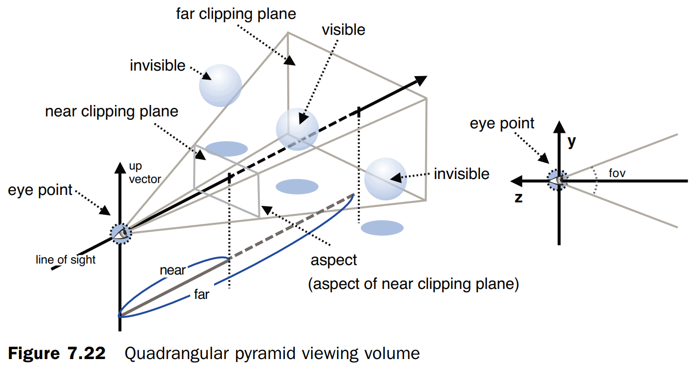
箱式视图体的理论结构:
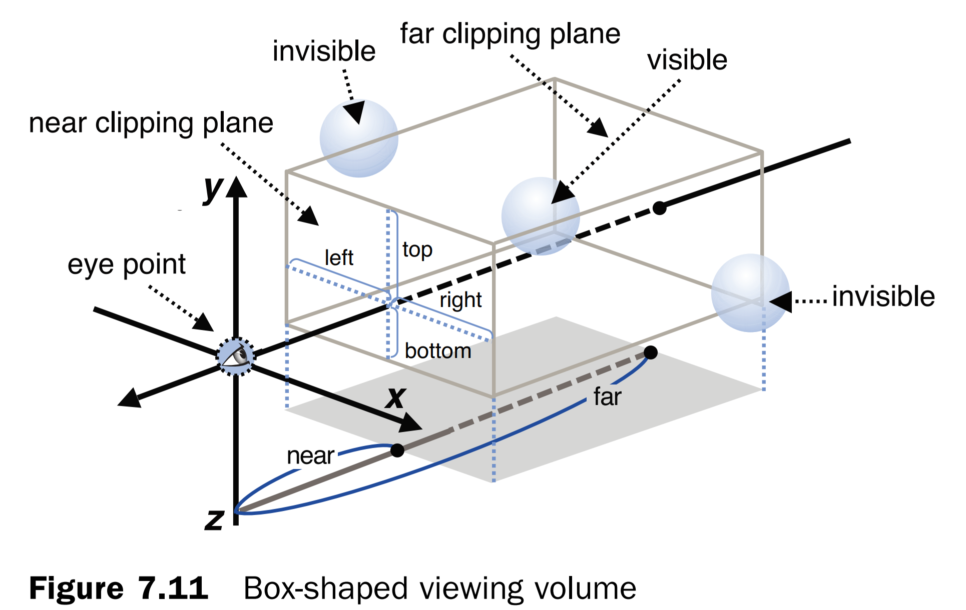
注意:近裁切面的纵横比例要与画布的纵横比例相同,否则会被拉伸。
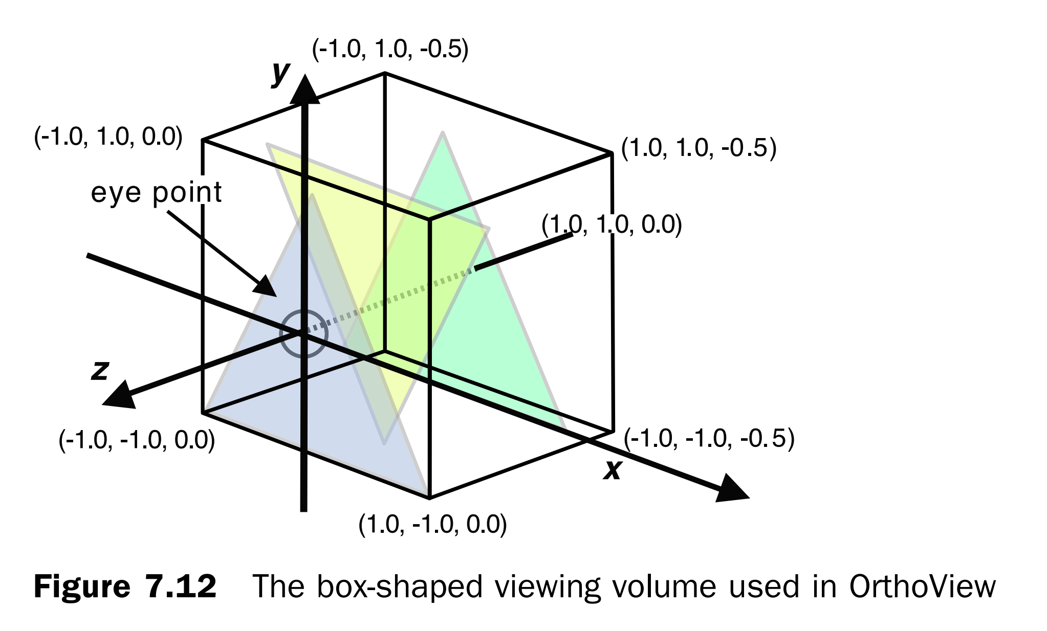
正交投影
正交投影中的箱式观察体。
示例程序
相比LookAtTrianglesWithKeys.js有如下变化:
1. 使用投影矩阵变量来代替原来的模型视图矩阵,在顶点着色器中。
// Vertex shader program
var VSHADER_SOURCE =
    'attribute vec4 a_Position;\n' +
    'attribute vec4 a_Color;\n' +
    'uniform mat4 u_ProjMatrix;\n' +
    'varying vec4 v_Color;\n' +
    'void main() {\n' +
    '   gl_Position = u_ProjMatrix * a_Position;\n' +
    '   v_Color = a_Color;\n' +
    '}\n';
2. 在按键的地方做了调整,左右键移动近裁切面,上下移动远裁切面。
// The distances to the near and far clipping plane
var g_near = 0.0, g_far = 0.5;
function keydown(ev, gl, n, u_ProjMatrix, projMatrix, nf) {
    switch(ev.keyCode) {
        case 39: g_near += 0.01; break; // The right arrow key was pressed
        case 37: g_near -= 0.01; break; // The left arrow key was pressed
        case 38: g_far += 0.01; break;  // The up arrow key was pressed
        case 40: g_far -= 0.01; break;  // The down arrow key was pressed
        default: return;                // Prevent the unnecessary drawing
    }
    draw(gl, n, u_ProjMatrix, projMatrix, nf);
}
3. 在绘图函数draw中,由视点矩阵改为正交投影矩阵。
    // Set the viewing volume using a matrix
    projMatrix.setOrtho(-1, 1, -1, 1, g_near, g_far);
    // Set the projection matrix to u_ProjMatrix variable
    gl.uniformMatrix4fv(u_ProjMatrix, false, projMatrix.elements);
4. 在main函数中,关联顶点着色器的投影矩阵
// Get the storage location of u_ProjMatrix variable
var u_ProjMatrix = gl.getUniformLocation(gl.program, 'u_ProjMatrix');
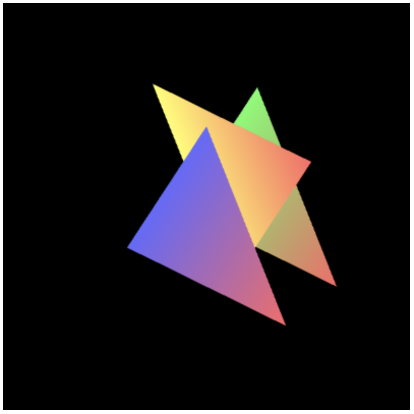
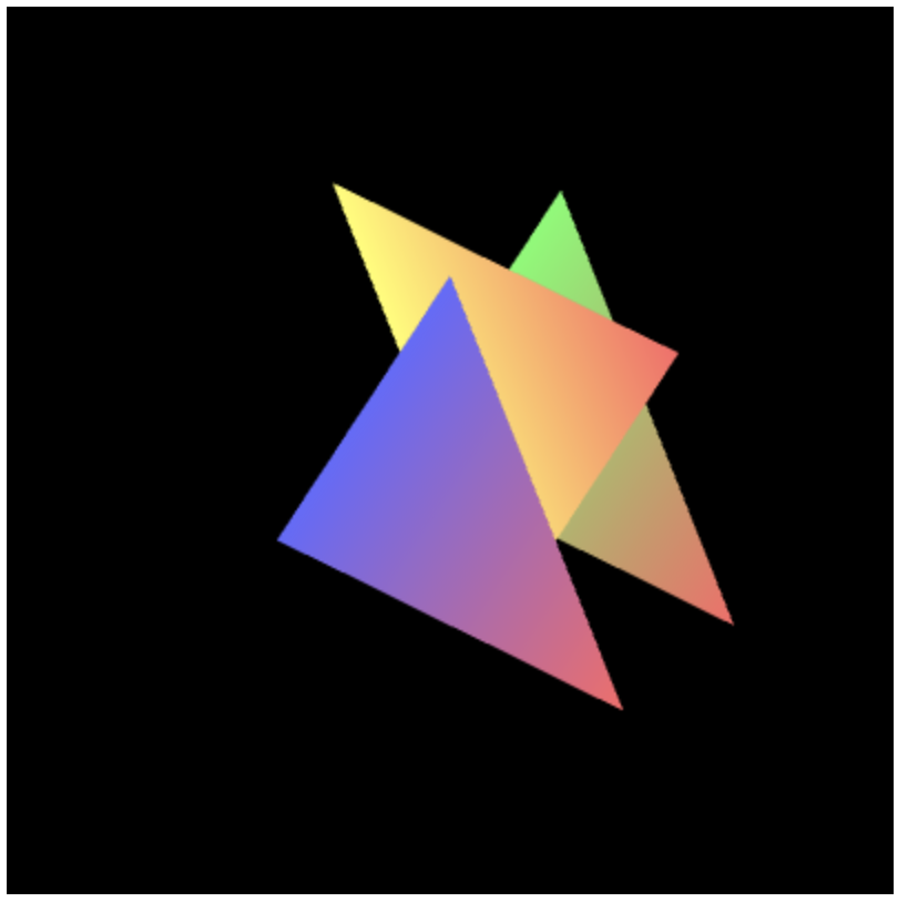
5. 设置最后一个三角形尺寸略微不同,以使在正交投影情况下能够看到最后一个三角形,防止相同大小被第一个三角形完全遮挡。
        // vertex coordinates and color
         0.0,  0.6, -0.4, 0.4, 1.0, 0.4, // The back green triangle
        -0.5, -0.4, -0.4, 0.4, 1.0, 0.4,
         0.5, -0.4, -0.4, 1.0, 0.4, 0.4,
完整代码
// OrthoView.js // Vertex shader program var VSHADER_SOURCE = 'attribute vec4 a_Position;\n' + 'attribute vec4 a_Color;\n' + 'uniform mat4 u_ProjMatrix;\n' + 'varying vec4 v_Color;\n' + 'void main() {\n' + ' gl_Position = u_ProjMatrix * a_Position;\n' + ' v_Color = a_Color;\n' + '}\n'; // Fragment shader program var FSHADER_SOURCE = '#ifdef GL_ES\n' + 'precision mediump float;\n' + '#endif\n' + 'varying vec4 v_Color;\n' + 'void main() {\n' + ' gl_FragColor = v_Color;\n' + '}\n'; function main() { // Retrieve element var canvas = document.getElementById('webgl'); // Retrieve the nearFar element var nf = document.getElementById('nearFar'); // Get the rendering context for WebGL var gl = getWebGLContext(canvas); if (!gl) { console.log('Failed to get the rendering context for WebGL'); return; } // Initialize shaders if (!initShaders(gl, VSHADER_SOURCE, FSHADER_SOURCE)) { console.log('Failed to initialize shaders.'); return; } // Set the vertex coordinates and color (blue triangle is in front) var n = initVertexBuffers(gl); if (n程序运行截图,左右键移动近裁切面,上下移动远裁切面:
移动近裁切面:
移动远裁切面:
恢复裁切
在前面的范例中,LookAtTrianglesWithKeys.js,当改变视点旋转三角形时,出现了裁切,如下图:
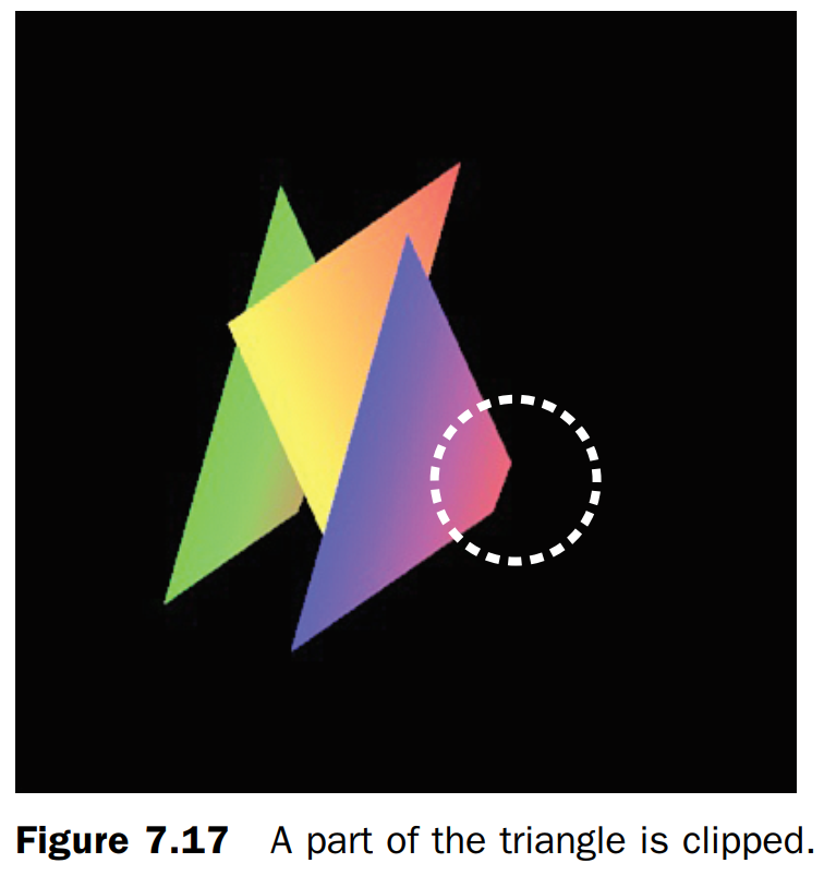
这是因为可视范围所致,调整远裁切平面即可。
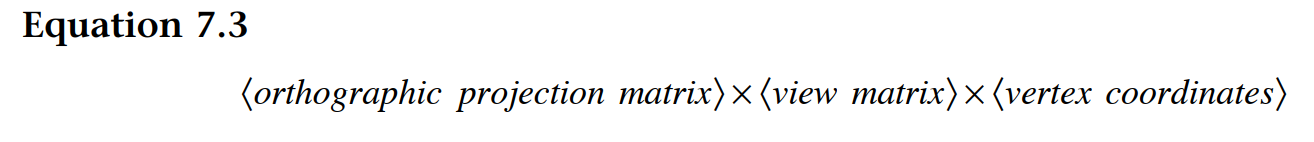
当投影矩阵、视图矩阵都存在时,则顶点着色器中使用方程7.3来组织gl_Position,如下图:
恢复裁切示例
LookAtTrianglesWithKeys_ViewVolume.js在LookAtTrianglesWithKeys.js上修改,并作如下变更:
1. 修改顶点着色器,将投影矩阵乘入gl_Position
// Vertex shader program var VSHADER_SOURCE = 'attribute vec4 a_Position;\n' + 'attribute vec4 a_Color;\n' + 'uniform mat4 u_ModelViewMatrix;\n' + 'uniform mat4 u_ProjMatrix;\n' + 'varying vec4 v_Color;\n' + 'void main() {\n' + ' gl_Position = u_ProjMatrix * u_ModelViewMatrix * a_Position;\n' + ' v_Color = a_Color;\n' + '}\n';2. 修改main(),关联投影矩阵
var u_ProjMatrix = gl.getUniformLocation(gl.program, 'u_ProjMatrix');
3. 设置正交投影矩阵,将远裁切平面设置成2.0,并传入给顶点着色器
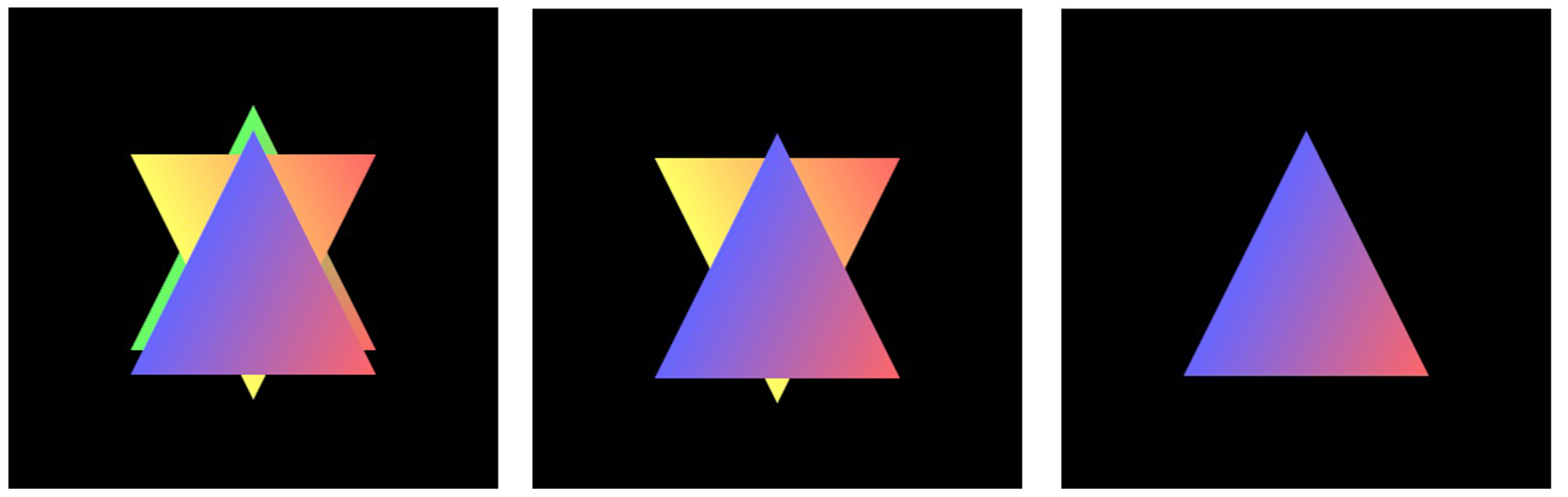
// Create the matrix to specify the viewing volume and pass it to u_ProjMatrix var projMatrix = new Matrix4(); projMatrix.setOrtho(-1.0, 1.0, -1.0, 1.0, 0.0, 2.0); gl.uniformMatrix4fv(u_ProjMatrix, false, projMatrix.elements);运行结果:左边为未设置投影矩阵,右边为设置了投影矩阵
投影扭曲
在范例OrthoView.js做修改并保存为OthoView_halfSize.js。调整其正交投影X,Y为原来的一半,即保持纵横比例,则运行结果如下方左图。
projMatrix.setOrtho(-0.5, 0.5, -0.5, 0.5, 0, 0.5);
当改动正交投影X,Y不同比例是,图像会被按比例拉伸,如下代码将X轴调整到-0.3,0.3,y轴保持-1.0,1.0,则图像X轴方向会被拉伸。如下方右图。
projMatrix.setOrtho(-0.3, 0.3, -1.0, 1.0, 0.0, 0.5);

透视投影(四棱锥观察体)
设置四棱锥观察体
透视投影前面两个参数使用了不同的定义。
fov: 视点的仰角; aspect: 近裁切平面的纵横比。
另外远裁切面必须大于近裁切面。
透视投影示例
修改LookAtTrianglesWithKeys_ViewVolume.js并另存为PerspectiveView.js。做如下修改
1. 修改main(),增加投影矩阵,并设置参数
var u_ProjMatrix = gl.getUniformLocation(gl.program, 'u_ProjMatrix'); // Create the matrix to specify the viewing volume and pass it to u_ProjMatrix var projMatrix = new Matrix4(); projMatrix.setPerspective(30, canvas.width/canvas.height, 1, 100); gl.uniformMatrix4fv(u_ProjMatrix, false, projMatrix.elements);
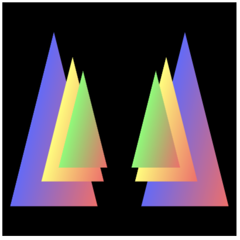
2. 设立左右两排“树木”,重新定义顶点数量
var verticesColors = new Float32Array([ // vertex coordinates and color // Three triangles on the right side 0.75, 1.0, -4.0, 0.4, 1.0, 0.4, // The green triangle in back 0.25, -1.0, -4.0, 0.4, 1.0, 0.4, 1.25, -1.0, -4.0, 1.0, 0.4, 0.4, 0.75, 1.0, -2.0, 1.0, 1.0, 0.4, // The yellow triangle in miiddle 0.25, -1.0, -2.0, 1.0, 1.0, 0.4, 1.25, -1.0, -2.0, 1.0, 0.4, 0.4, 0.75, 1.0, 0.0, 0.4, 0.4, 1.0, // The blue triangle in front 0.25, -1.0, 0.0, 0.4, 0.4, 1.0, 1.25, -1.0, 0.0, 1.0, 0.4, 0.4, // Three triangles on the left side -0.75, 1.0, -4.0, 0.4, 1.0, 0.4, // The back green one -1.25, -1.0, -4.0, 0.4, 1.0, 0.4, -0.25, -1.0, -4.0, 1.0, 0.4, 0.4, -0.75, 1.0, -2.0, 1.0, 1.0, 0.4, // The middle yellow one -1.25, -1.0, -2.0, 1.0, 1.0, 0.4, -0.25, -1.0, -2.0, 1.0, 0.4, 0.4, -0.75, 1.0, 0.0, 0.4, 0.4, 1.0, // The front blue one -1.25, -1.0, 0.0, 0.4, 0.4, 1.0, -0.25, -1.0, 0.0, 1.0, 0.4, 0.4, ]); var n = 18;3. 去掉按键事件
运行结果

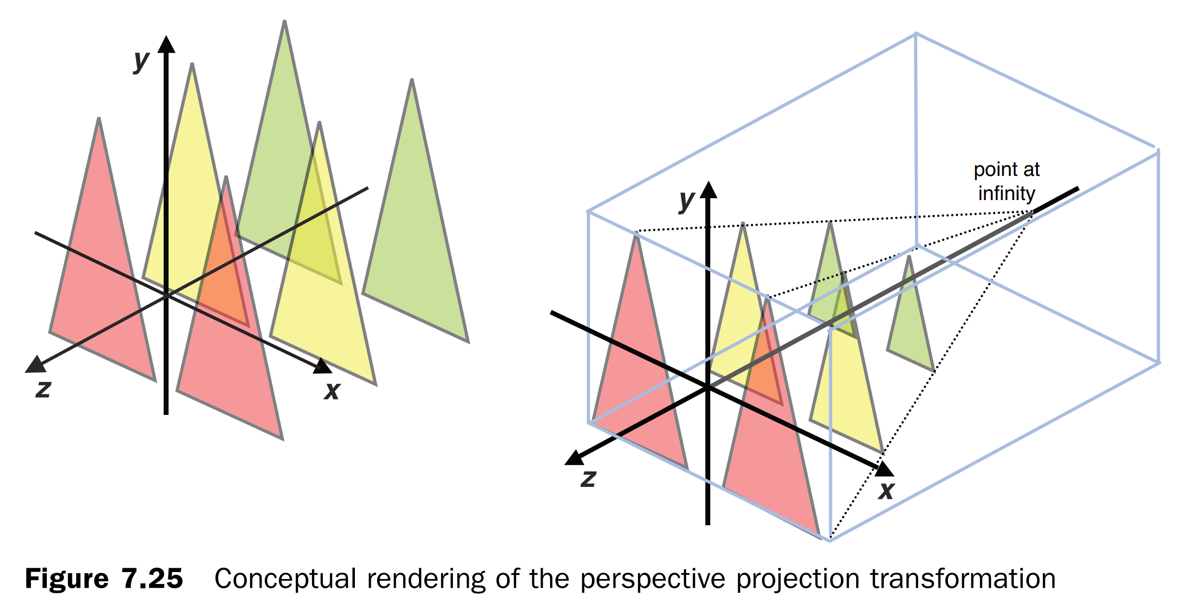
投影矩阵的作用
透视投影矩阵将依据参数自动计算远程物体的大小,完成后转成四棱锥观察体。
使用所有矩阵(模型矩阵、视图矩阵、投影矩阵)

示例程序
在PerspectiveView.js上修改而来,并保存为PerspectiveView_mvp.js。其差别为:
1. 顶点着色器上使用了方程7.4的方法,gl_Position = 投影矩阵 * 视图矩阵 * 模型矩阵 * a_Position。如下:
// Vertex shader program var VSHADER_SOURCE = 'attribute vec4 a_Position;\n' + 'attribute vec4 a_Color;\n' + 'uniform mat4 u_ModelMatrix;\n' + 'uniform mat4 u_ViewMatrix;\n' + 'uniform mat4 u_ProjMatrix;\n' + 'varying vec4 v_Color;\n' + 'void main() {\n' + ' gl_Position = u_ProjMatrix * u_ViewMatrix * u_ModelMatrix * a_Position;\n' + ' v_Color = a_Color;\n' + '}\n';2. 在main中添加模型矩阵,并用来关联:
var u_ModelMatrix = gl.getUniformLocation(gl.program, 'u_ModelMatrix'); ... var modelMatrix = new Matrix4(); // Model matrix ... modelMatrix.setTranslate(0.75, 0, 0); // Translate 0.75 units ... gl.uniformMatrix4fv(u_ModelMatrix, false, modelMatrix.elements); gl.clear(gl.COLOR_BUFFER_BIT); // Clear gl.drawArrays(gl.TRIANGLES, 0, n); // Draw triangles on right // Prepare the model matrix for another pair of triangles modelMatrix.setTranslate(-0.75, 0, 0); // Translate -0.75 // Modify only the model matrix gl.uniformMatrix4fv(u_ModelMatrix, false, modelMatrix.elements); gl.drawArrays(gl.TRIANGLES, 0, n); // Draw triangles on left3. 在initVertexBuffers中,修改了顶点,仅定义了在z轴居中的三个三角形,顶点数量n=9
var verticesColors = new Float32Array([ // vertex coordinates and color 0.0, 1.0, -4.0, 0.4, 1.0, 0.4, // The back green triangle -0.5, -1.0, -4.0, 0.4, 1.0, 0.4, 0.5, -1.0, -4.0, 1.0, 0.4, 0.4, 0.0, 1.0, -2.0, 1.0, 1.0, 0.4, // The middle yellow triangle -0.5, -1.0, -2.0, 1.0, 1.0, 0.4, 0.5, -1.0, -2.0, 1.0, 0.4, 0.4, 0.0, 1.0, 0.0, 0.4, 0.4, 1.0, // The front blue triangle -0.5, -1.0, 0.0, 0.4, 0.4, 1.0, 0.5, -1.0, 0.0, 1.0, 0.4, 0.4, ]); var n = 9;运行结果同PerspectiveView.js。
将mvp矩阵在着色器外计算
在PerspectiveView_mvp.js修改并保存为PerspectiveView_mvpMatrix.js。将矩阵计算从顶点着色器里取出来,在javascript中计算出结果后再传入到顶点着色器中。与PerspectiveView_mvp的区别:
1. 顶点着色器使用单个u_mvpMatrix矩阵将javascipt中计算的投影矩阵*视图矩阵*模型矩阵的结果送入到顶点着色器。
// Vertex shader program var VSHADER_SOURCE = 'attribute vec4 a_Position;\n' + 'attribute vec4 a_Color;\n' + 'uniform mat4 u_mvpMatrix;\n' + 'varying vec4 v_Color;\n' + 'void main() {\n' + ' gl_Position = u_mvpMatrix* a_Position;\n' + ' v_Color = a_Color;\n' + '}\n';2. 在main函数中仅使用单个u_mvpMatrix关联顶点着色器。并直接在javascript中将计算结果算出来保存在mvpMatrix中,最后送入顶点着色器
var u_mvpMatrix = gl.getUniformLocation(gl.program, 'u_mvpMatrix'); ... var modelMatrix = new Matrix4(); // Model matrix var viewMatrix = new Matrix4(); // View matrix var projMatrix = new Matrix4(); // Projection matrix var mvpMatrix = new Matrix4(); // The moodel view projection matrix ... modelMatrix.setTranslate(0.75, 0, 0); // Translate 0.75 units viewMatrix.setLookAt(0, 0, 5, 0, 0, -100, 0, 1, 0); projMatrix.setPerspective(30, canvas.width/canvas.height, 1, 100); mvpMatrix.set(projMatrix).multiply(viewMatrix).multiply(modelMatrix); gl.uniformMatrix4fv(u_mvpMatrix, false, mvpMatrix.elements); gl.clear(gl.COLOR_BUFFER_BIT); // Clear gl.drawArrays(gl.TRIANGLES, 0, n); // Draw triangles on right // Prepare the model matrix for another pair of triangles modelMatrix.setTranslate(-0.75, 0, 0); // Translate -0.75 // Calculate the model view projection matrix mvpMatrix.set(projMatrix).multiply(viewMatrix).multiply(modelMatrix); // Modify only the model matrix gl.uniformMatrix4fv(u_mvpMatrix, false, mvpMatrix.elements); gl.drawArrays(gl.TRIANGLES, 0, n); // Draw triangles on left
运行结果同PerspectiveView.js。
正确处理前景和后景物体
为了提高效率,webgl默认情况下是按顶点出现的顺序绘图。当上例PerspectiveView_mvpMatrix.js中交换前面的蓝色和最后面的绿色三角形顺序时,
var verticesColors = new Float32Array([ // vertex coordinates and color 0.0, 1.0, 0.0, 0.4, 0.4, 1.0, // The front blue triangle -0.5, -1.0, 0.0, 0.4, 0.4, 1.0, 0.5, -1.0, 0.0, 1.0, 0.4, 0.4, 0.0, 1.0, -2.0, 1.0, 1.0, 0.4, // The middle yellow triangle -0.5, -1.0, -2.0, 1.0, 1.0, 0.4, 0.5, -1.0, -2.0, 1.0, 0.4, 0.4, 0.0, 1.0, -4.0, 0.4, 1.0, 0.4, // The back green triangle -0.5, -1.0, -4.0, 0.4, 1.0, 0.4, 0.5, -1.0, -4.0, 1.0, 0.4, 0.4, ]);后面的绿色三角形绘制的时候会覆盖前面蓝色三角形的区域。如下图所示:
隐藏面消除
为了避免上面这个问题,webgl提供了深度检测(或称之为z检测)。这样不管顶点出现的顺序都能够从视点出发得到一个正确的绘制结果。开启深度检测需要经过两个步骤:
- gl.enable(gl.DEPTH_TEST);
- gl.clear(gl.DEPTH_BUFFER_BIT);
示例程序(深度缓存)
此示例由上面示例改动而来,除了蓝色和绿色三角形维持外,增加了深度检测以及清除深度缓冲区。
// Enable the hidden surface removal function gl.enable(gl.DEPTH_TEST); ... // Clear the depth buffer gl.clear(gl.COLOR_BUFFER_BIT | gl.DEPTH_BUFFER_BIT);
开启后,则就能够正确绘制图像,而不需考虑顶点出现的顺序。程序运行结果同PerspectiveView.js 。
z冲突
当两个图形在Z轴挨得很近的时候,使用深度检测时,webgl有时无法确定要覆盖的部分,如下图所示。
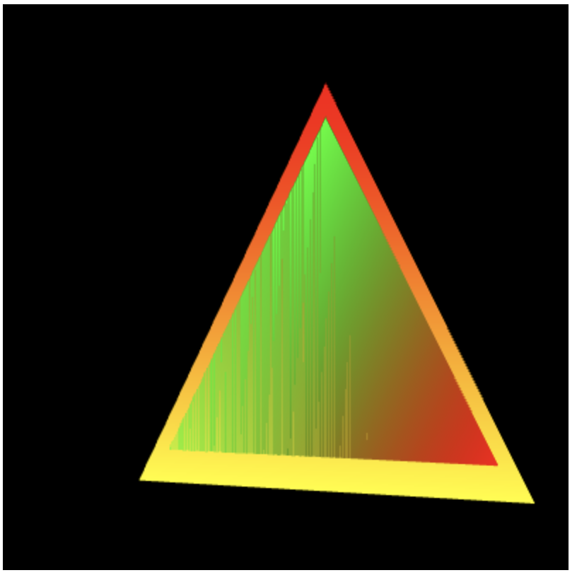
在这个示例中,z轴使用了相同的位置,且设定了视点位置,使其焦点在(0,0,-3)如下代码:
function main() { ... viewMatrix.setLookAt(4, 0, 10, 0, 0, -3, 0, 1, 0); projMatrix.setPerspective(30, canvas.width/canvas.height, 1, 100); ... } function initVertexBuffers(gl) { var verticesColors = new Float32Array([ // vertex coordinates and color 0.0, 2.5, -5.0, 0.0, 1.0, 0.0, // The green triangle -2.5, -2.5, -5.0, 0.0, 1.0, 0.0, 2.5, -2.5, -5.0, 1.0, 0.0, 0.0, 0.0, 3.0, -5.0, 1.0, 0.0, 0.0, // The yellow triangle -3.0, -3.0, -5.0, 1.0, 1.0, 0.0, 3.0, -3.0, -5.0, 1.0, 1.0, 0.0 ]); var n = 6; ... }为了避免这个问题,使用了多边形偏移量设置,如下代码:
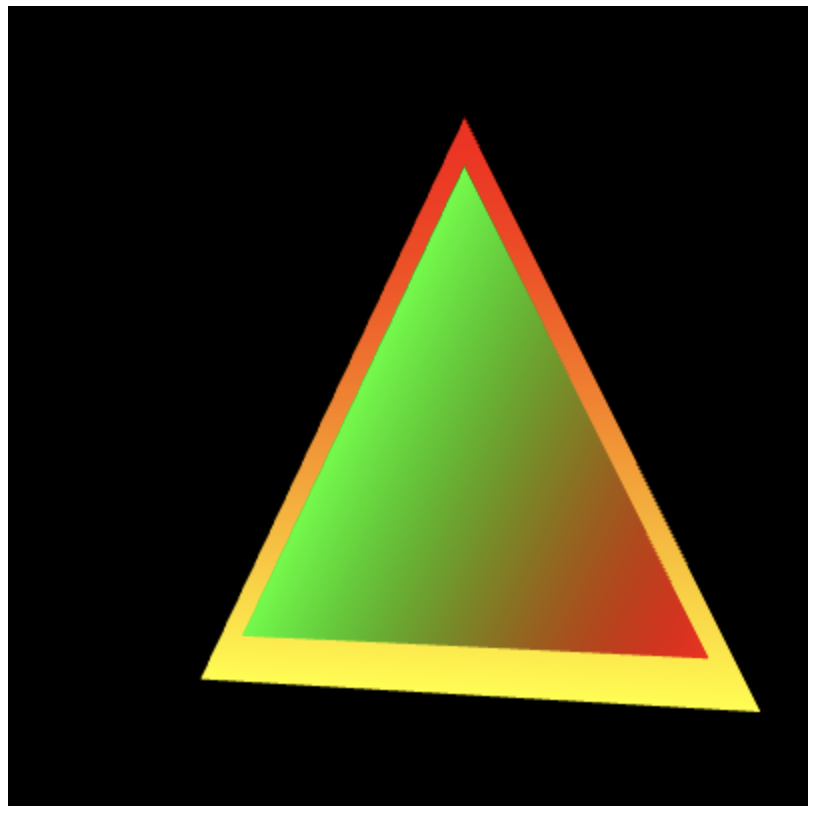
function main() { ... // Enable the polygon offset function gl.enable(gl.POLYGON_OFFSET_FILL); // Draw a rectangle gl.drawArrays(gl.TRIANGLES, 0, n /2); // The green triangle gl.polygonOffset(1.0, 1.0); // Set the polygon offset gl.drawArrays(gl.TRIANGLES, n/2, n/2); // The yellow triangle }首先开启多边形偏移量设置,然后每次绘制前设定偏移量。偏移量有两个参数,第一个参数为偏移因子factor,第二个参数为偏移单位units。webgl实际在计算时使用
m * factor + r * units
来计算,其中m表示三角形相对于视线的倾斜度,r是硬件可以区分的两个z坐标值之间的最小差。运行结果如下图
立方体
一个面需要2个三角形,即6个顶点坐标,一个立方体有6个面,就有36个顶点坐标。而实际上这些点是共用的,最终只会用到8个点。
使用索引和顶点坐标绘制物体
为了提高效率,采用顶点索引。在绘制的使用不使用gl.drawArrays而使用gl.drawElements。它有4个参数,分别为:图元形状,数量,索引数据类型,偏移量。
gl.drawElements(mode, count, type, offset)
其中图元类型包括:gl.POINTS, gl.LINE_STRIP, gl.LINE_LOOP, gl.LINES, gl.TRIANGLE_STRIP, gl.TRIANGLE_FAN, or gl.TRIANGLES
索引数据类型包括:gl.UNSIGNED_BYTE、gl.UNSIGNED_SHORT
示例程序
这里使用基于ProjectiveView_mvpMatrix.js改为HelloCube.js。一共n处修改:
1. 开启深度检测,因为绘制立方体时需要用到深度检测。绘制前清除深度缓冲区
function main() { ... gl.enable(gl.DEPTH_TEST); ... gl.clear(gl.COLOR_BUFFER_BIT | gl.DEPTH_BUFFER_BIT); // Clear ... }2. 设置模型视图投影矩阵,并设置相关参数
function main() { ... var mvpMatrix = new Matrix4(); mvpMatrix.setPerspective(30, 1, 1, 100); mvpMatrix.lookAt(3, 3, 7, 0, 0, 0, 0, 1, 0); ... }3. 使用gl.drawElements来绘制图形
function main() { ... gl.drawElements(gl.TRIANGLES, n, gl.UNSIGNED_BYTE, 0); }4. 在初始化顶点缓冲区函数(initVertexBuffers)中,增加了顶点索引
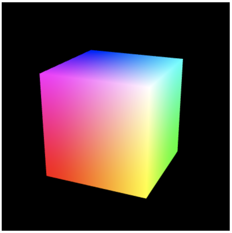
function initVertexBuffer(gl) { // v6----- v5 // /| /| // v1------v0| // | | | | // | |v7---|-|v4 // |/ |/ // v2------v3 var verticesColors = new Float32Array([ // Vertex coordinates and color 1.0, 1.0, 1.0, 1.0, 1.0, 1.0, // v0 White -1.0, 1.0, 1.0, 1.0, 0.0, 1.0, // v1 Magenta -1.0, -1.0, 1.0, 1.0, 0.0, 0.0, // v2 Red 1.0, -1.0, 1.0, 1.0, 1.0, 0.0, // v3 Yellow 1.0, -1.0, -1.0, 0.0, 1.0, 0.0, // v4 Green 1.0, 1.0, -1.0, 0.0, 1.0, 1.0, // v5 Cyan -1.0, 1.0, -1.0, 0.0, 0.0, 1.0, // v6 Blue -1.0, -1.0, -1.0, 0.0, 0.0, 0.0 // v7 Black ]); // Indices of the vertices var indices = new Uint8Array([ 0, 1, 2, 0, 2, 3, // front 0, 3, 4, 0, 4, 5, // right 0, 5, 6, 0, 6, 1, // up 1, 6, 7, 1, 7, 2, // left 7, 4, 3, 7, 3, 2, // down 4, 7, 6, 4, 6, 5 // back ]); ... }5. 在顶点着色器中使用ELEMENT_ARRAY_BUFFER来绑定到索引缓冲区,最后写入缓冲数据并返回索引长度。
function initVertexBuffer(gl) { ... var indexBuffer = gl.createBuffer(); ... // Write the indices to the buffer object gl.bindBuffer(gl.ELEMENT_ARRAY_BUFFER, indexBuffer); gl.bufferData(gl.ELEMENT_ARRAY_BUFFER, indices, gl.STATIC_DRAW); return indices.length; }程序运行截图:
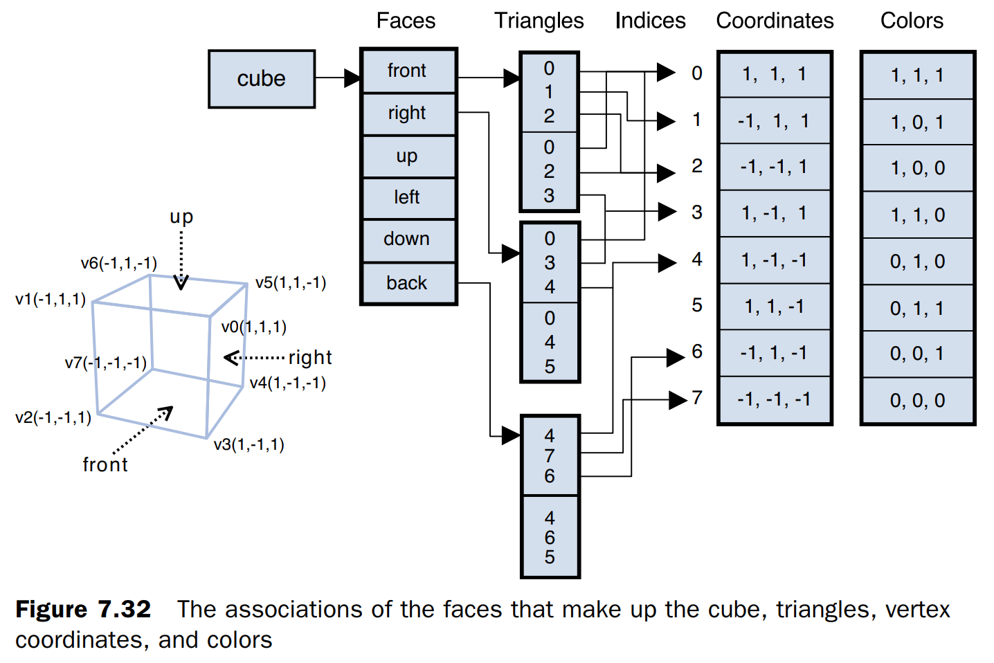
将顶点坐标、颜色、索引写入到缓冲区对象
上上面的例子中,顶点坐标、颜色写入到gl.ARRAY_BUFFER,然后使用索引列表绑定到gl.ELEMENT_ARRAY_BUFFER,这样,在缓冲区对象中就可以使用索引从gl.ARRAY_BUFFER中读取坐标和颜色。如下图所示。
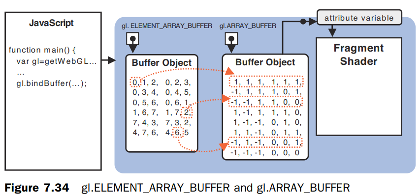
而此时的gl.drawElements(gl.TRIANGLES, n, gl.UNSIGNED_BYTE, 0);中的n是指的索引表长度。
另外在索引表建立的时候如果使用了
var indices = new Uint8Array([ ... ]);则最大只支持28即256个索引,超过的需要使用Uint16Array,其最大支持65535个索引。
var indices = new Uint16Array([ ... ]);在gl.drawElements(gl.TRIANGLES, n, gl.UNSIGNED_BYTE, 0);的第3个参数。gl.UNSIGNED_BYTE对应的是Uint8Array;gl.UNSIGNED_SHORT对应的是Uint16Array。
为立方体每个面添加颜色
由于立方体的点对于每个面是共用的,所以若某个点指定了红色,那么对于它的侧面如果要指定另一个颜色必须分离点坐标。对于纹理映射相同的道理。
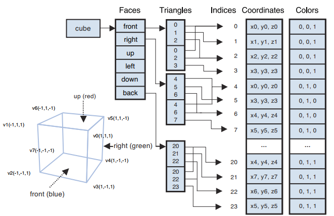
为此,如果需要对立方体每个面指定不同颜色,那么得将24个三角形顶点全部分离,如下所示。
示例程序(指定颜色的立方体)
在上一个例子HelloCube.js上做修改,并保存为ColoredCube.js。做如下修改
1. 在initVertexBuffers中,顶点坐标和颜色坐标分离,各自独立的数组。
var verticesColors = new Float32Array([ // Vertex coordinates 1.0, 1.0, 1.0, -1.0, 1.0, 1.0, -1.0,-1.0, 1.0, 1.0,-1.0, 1.0, // v0-v1-v2-v3 front 1.0, 1.0, 1.0, 1.0,-1.0, 1.0, 1.0,-1.0,-1.0, 1.0, 1.0,-1.0, // v0-v3-v4-v5 right 1.0, 1.0, 1.0, 1.0, 1.0,-1.0, -1.0, 1.0,-1.0, -1.0, 1.0, 1.0, // v0-v5-v6-v1 up -1.0, 1.0, 1.0, -1.0, 1.0,-1.0, -1.0,-1.0,-1.0, -1.0,-1.0, 1.0, // v1-v6-v7-v2 left -1.0,-1.0,-1.0, 1.0,-1.0,-1.0, 1.0,-1.0, 1.0, -1.0,-1.0, 1.0, // v7-v4-v3-v2 down 1.0,-1.0,-1.0, -1.0,-1.0,-1.0, -1.0, 1.0,-1.0, 1.0, 1.0,-1.0 // v4-v7-v6-v5 back ]); var colors = new Float32Array([ // Colors 0.4, 0.4, 1.0, 0.4, 0.4, 1.0, 0.4, 0.4, 1.0, 0.4, 0.4, 1.0, // v0-v1-v2-v3 front(blue) 0.4, 1.0, 0.4, 0.4, 1.0, 0.4, 0.4, 1.0, 0.4, 0.4, 1.0, 0.4, // v0-v3-v4-v5 right(green) 1.0, 0.4, 0.4, 1.0, 0.4, 0.4, 1.0, 0.4, 0.4, 1.0, 0.4, 0.4, // v0-v5-v6-v1 up(red) 1.0, 1.0, 0.4, 1.0, 1.0, 0.4, 1.0, 1.0, 0.4, 1.0, 1.0, 0.4, // v1-v6-v7-v2 left 1.0, 1.0, 1.0, 1.0, 1.0, 1.0, 1.0, 1.0, 1.0, 1.0, 1.0, 1.0, // v7-v4-v3-v2 down 0.4, 1.0, 1.0, 0.4, 1.0, 1.0, 0.4, 1.0, 1.0, 0.4, 1.0, 1.0 // v4-v7-v6-v5 back ]);2. 在initVertexBuffers中重新定义24个三角形顶点索引。
var indices = new Uint8Array([ // Indices of the vertices 0, 1, 2, 0, 2, 3, // front 4, 5, 6, 4, 6, 7, // right 8, 9,10, 8,10,11, // up 12,13,14, 12,14,15, // left 16,17,18, 16,18,19, // down 20,21,22, 20,22,23 // back ]);3. 定义一个initArrayBuffer函数,在initVertexBuffers中调用它并让其绑定到缓冲区对象上。
// Write the vertex coordinates and color to the buffer object if (!initArrayBuffer(gl, verticesColors, 3, gl.FLOAT, 'a_Position')) return -1; if (!initArrayBuffer(gl, colors, 3, gl.FLOAT, 'a_Color')) return -1;4. 在initArrayBuffer函数,绑定缓冲区,数据写入缓冲区,绑定到顶点着色器变量,最后启动缓冲区。
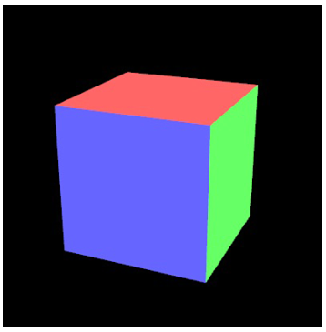
function initArrayBuffer(gl, data, num, type, attribute) { var buffer = gl.createBuffer(); // Create a buffer object if ((!buffer)) { console.log('Failed to create the buffer object'); return false; } // Write the vertex coordinates and color to the buffer object gl.bindBuffer(gl.ARRAY_BUFFER, buffer); gl.bufferData(gl.ARRAY_BUFFER, data, gl.STATIC_DRAW); // Assign the buffer object to the attribute variable var a_attribute = gl.getAttribLocation(gl.program, attribute); if (a_attribute程序运行截图:
立方体所有面指定相同颜色
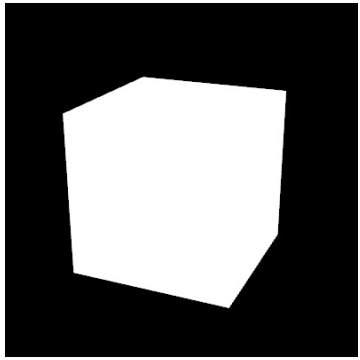
当立方体所有面指定相同颜色时,由于确发光照即法向量定义,则看起来是个平面。
此例通过修改ColoredCube.js并保存为ColoredCube_SingleColor.js,这里仅修改了颜色,是所有面均为白色。
var colors = new Float32Array([ // Colors 1.0, 1.0, 1.0, 1.0, 1.0, 1.0, 1.0, 1.0, 1.0, 1.0, 1.0, 1.0, // v0-v1-v2-v3 front(blue) 1.0, 1.0, 1.0, 1.0, 1.0, 1.0, 1.0, 1.0, 1.0, 1.0, 1.0, 1.0, // v0-v3-v4-v5 right(green) 1.0, 1.0, 1.0, 1.0, 1.0, 1.0, 1.0, 1.0, 1.0, 1.0, 1.0, 1.0, // v0-v5-v6-v1 up(red) 1.0, 1.0, 1.0, 1.0, 1.0, 1.0, 1.0, 1.0, 1.0, 1.0, 1.0, 1.0, // v1-v6-v7-v2 left 1.0, 1.0, 1.0, 1.0, 1.0, 1.0, 1.0, 1.0, 1.0, 1.0, 1.0, 1.0, // v7-v4-v3-v2 down 1.0, 1.0, 1.0, 1.0, 1.0, 1.0, 1.0, 1.0, 1.0, 1.0, 1.0, 1.0 // v4-v7-v6-v5 back ]);程序运行结果如下图所示
Chapter 8 照明对象
3D照明对象
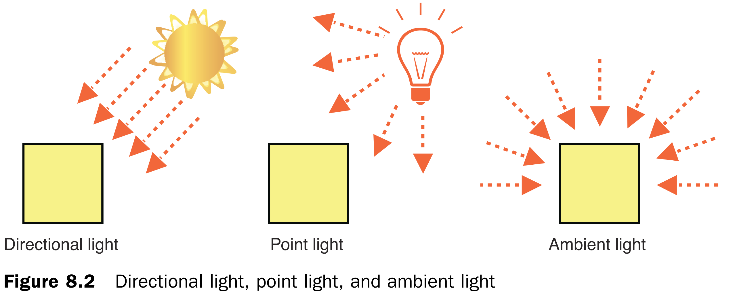
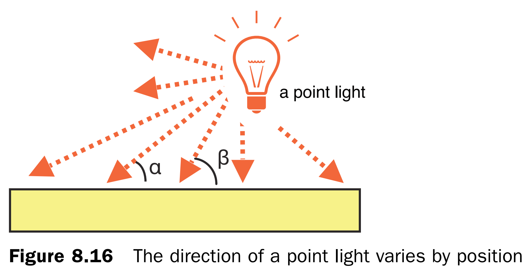
光源类型
光源类型分为平行光源、点光源、环境光源。
反射光类型
漫反射
漫反射是光源照射到物体上时物体的反射光。光源照射在物体上会被均匀反射也称之为散射。光源与曲面法向量之间的夹角称之为入射角。
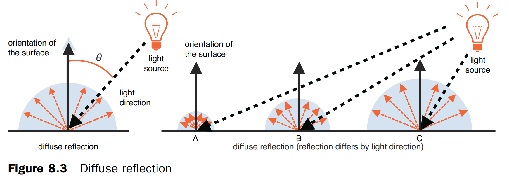
漫贩色表面的颜色=光源颜色*表面颜色*cosθ,其中θ为入射角。

环境反射
环境反射是反射另一光源的反射光。其入射角等于反射角。曲面环境反射颜色=光线颜色*曲面表面颜色。
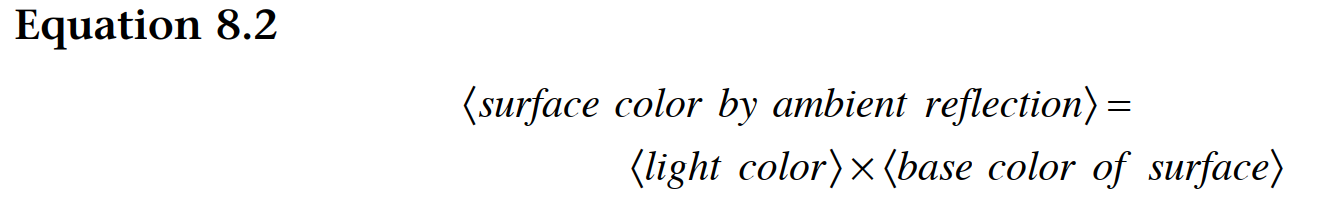
当环境反射的颜色和漫反射叠加叠加在一起时,则物体颜色=漫反射颜色+环境反射颜色。
使用光方向和表面方向计算漫反射
由两向量之间的夹角cosθ可以通过n•v=cos θ来表达;其中•为向量点乘。由此可知,光线与曲面法线的夹角cosθ可以表示为:

带入方程8.1得:

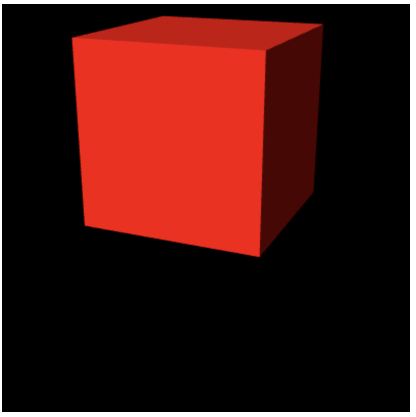
示例程序:被光照的立方体
程序在ColoredCube_SingleColor.js上修改并保存为LightedCube.js。修改内容如下:
1. 修改顶点着色器,使其支持曲面法向量、光源颜色、光源朝向三个栏目。
'attribute vec4 a_Normal;\n' + // surface orientation 'uniform vec3 u_LightColor;\n' + // Light color 'uniform vec3 u_LightDirection;\n' + // world coordinated, normalized将曲面法向量单位化处理。由于a_Normal是vec4类型这里单位化的曲面法向量是vec3 类型所以需要类型转换一下:
' vec3 normal = normalize(vec3(a_Normal));\n' +
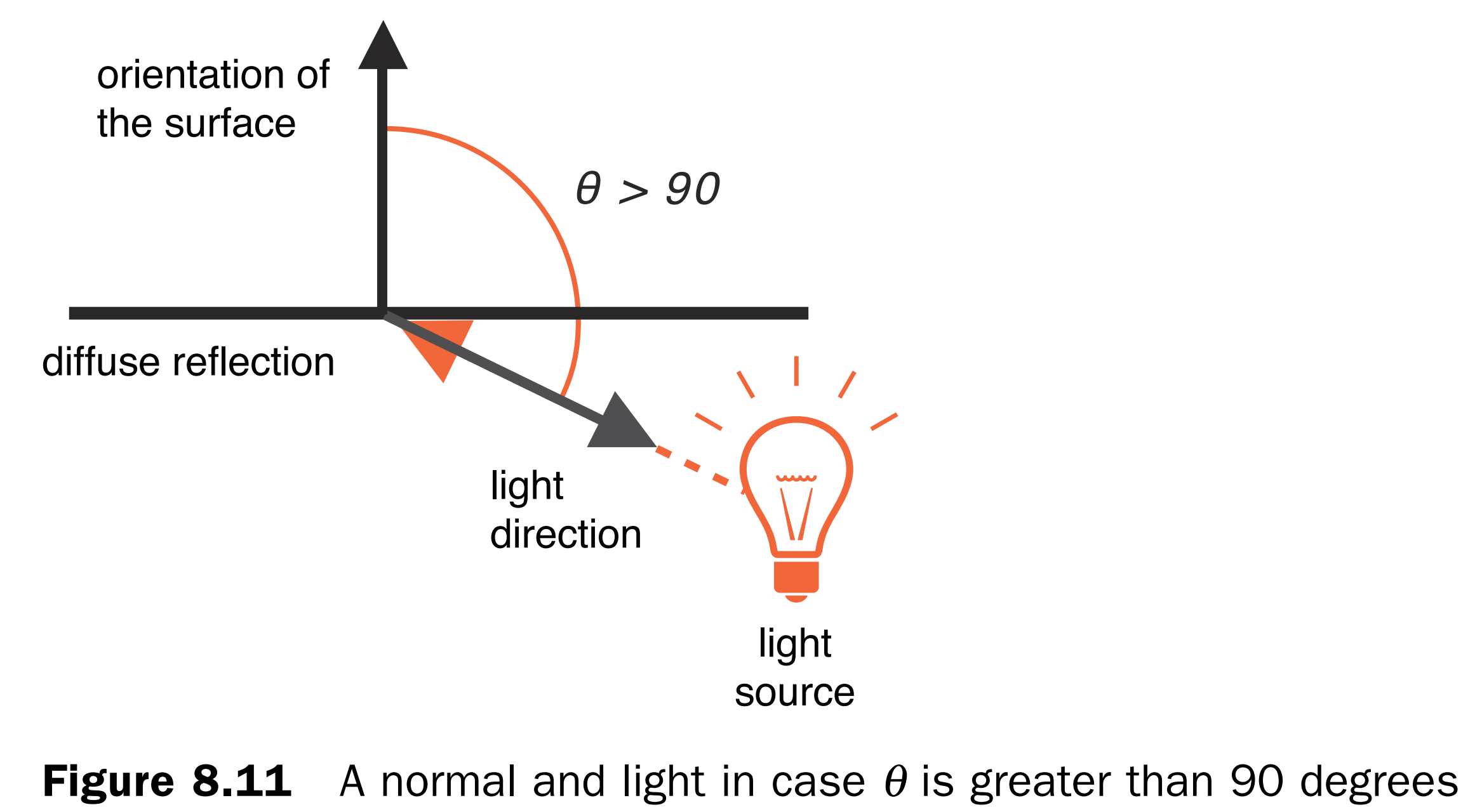
然后求出光线与曲面的夹角 cosθ,需要注意的是,这里使用的内置函数dot点乘操作符。另外为防止计算出负数,这里限制了最小值=0。因为负数表示光线照射到曲面的背面。
' float nDotL = max(dot(u_LightDirection, normal), 0.0);\n' +
然后利用方程8.1计算物体漫反射颜色,需要注意的是这里将a_Color的Alpha色去掉了,因为光源颜色是vec3类型。
' vec3 diffuse = u_LightColor * vec3(a_Color) * nDotL;\n' +
最后将漫反射颜色赋值给v_Color,这里将vec3类型的漫反射颜色和原本曲面表面的Alpha颜色重新组合成vec4类型:
' v_Color = vec4(diffuse, a_Color.a);\n' +
完整的顶点着色器代码如下:
var VSHADER_SOURCE = 'attribute vec4 a_Position;\n' + 'attribute vec4 a_Color;\n' + // surface base color 'attribute vec4 a_Normal;\n' + // surface orientation 'uniform mat4 u_mvpMatrix;\n' + 'uniform vec3 u_LightColor;\n' + // Light color 'uniform vec3 u_LightDirection;\n' + // world coordinated, normalized 'varying vec4 v_Color;\n' + 'void main() {\n' + ' gl_Position = u_mvpMatrix * a_Position;\n' + // Make the length of the normal 1.0 ' vec3 normal = normalize(vec3(a_Normal));\n' + // Dot product of light direction and orientation of a surface ' float nDotL = max(dot(u_LightDirection, normal), 0.0);\n' + // Calculate the color due to diffuse reflection ' vec3 diffuse = u_LightColor * vec3(a_Color) * nDotL;\n' + ' v_Color = vec4(diffuse, a_Color.a);\n' + '}\n';2. 在main()函数中定义了光源颜色、光照方向。然后将光照方向单位化处理并与前面定义的统一变量绑定传递给顶点着色器。
function main() { ... var u_LightColor = gl.getUniformLocation(gl.program, 'u_LightColor'); var u_LightDirection = gl.getUniformLocation(gl.program, 'u_LightDirection'); ... // Set the light color (white) gl.uniform3f(u_LightColor, 1.0, 1.0, 1.0); // Set the light direction (in the world coordinate) var lightDirection = new Vector3([0.5, 3.0, 4.0]); lightDirection.normalize(); // Normalize gl.uniform3fv(u_LightDirection, lightDirection.elements); ... }3. 在函数initVertexBuffers()中定义曲面法向量,并利用函数initArrayBuffer()绑定到顶点着色器的属性变量a_Normal上。
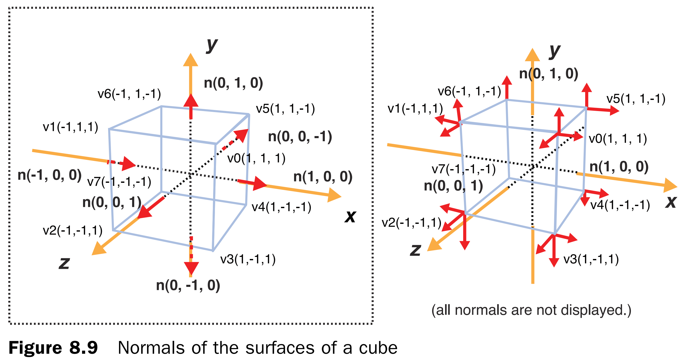
function initVertexBuffers(gl) { ... var normals = new Float32Array([ // Normal 0.0, 0.0, 1.0, 0.0, 0.0, 1.0, 0.0, 0.0, 1.0, 0.0, 0.0, 1.0, // v0-v1-v2-v3 front 1.0, 0.0, 0.0, 1.0, 0.0, 0.0, 1.0, 0.0, 0.0, 1.0, 0.0, 0.0, // v0-v3-v4-v5 right 0.0, 1.0, 0.0, 0.0, 1.0, 0.0, 0.0, 1.0, 0.0, 0.0, 1.0, 0.0, // v0-v5-v6-v1 up -1.0, 0.0, 0.0, -1.0, 0.0, 0.0, -1.0, 0.0, 0.0, -1.0, 0.0, 0.0, // v1-v6-v7-v2 left 0.0,-1.0, 0.0, 0.0,-1.0, 0.0, 0.0,-1.0, 0.0, 0.0,-1.0, 0.0, // v7-v4-v3-v2 down 0.0, 0.0,-1.0, 0.0, 0.0,-1.0, 0.0, 0.0,-1.0, 0.0, 0.0,-1.0 // v4-v7-v6-v5 back ]); ... if (!initArrayBuffer(gl, 'a_Normal', normals, 3, gl.FLOAT)) return -1; ... }值得注意的是,立方体上的法向量的指向如图所示。
程序运行结果如下图所示:

让立方体旋转
为了让立方体绕y轴旋转,参考了对4章的三角形动画内容,在main()函数中创建一个tick()函数,然后用逝去的时间计算旋转的角度。
在LightedCube.js上做修改,并保存为LightedCube_animation.js。具体调整如下:
1. 在main()函数中创建用来保存当前角度的变量、模型矩阵、法向量矩阵:
function main() { ... var currentAngle = 0.0; // Current rotation angle var modelMatrix = new Matrix4(); // Model matrix var mvpMatrix = new Matrix4(); // Model view projection matrix var normalMatrix = new Matrix4(); // Transformation matrix for normals ... }2. 创建tick函数,用来绘制画面。首先从逝去时间里获得一个新的当前角度。然后让模型矩阵绕Y轴旋转。接着设置模型试图矩阵,让其依据模型旋转后的位置重新设置改矩阵,并传回给顶点着色器。
对于法向量矩阵,需要将旋转后的模型矩阵求逆矩阵,然后转置(可见下一节)。将转置后的法向量矩阵传递给顶点着色器。
最后通过请求动画帧(requestAnimationFrame)来重新绘制下一个画面。
function main() { ... var tick = function() { currentAngle = animate(currentAngle); // Update the rotation angle // Calculate the model matrix modelMatrix.setRotate(currentAngle, 0, 1, 0); // Rotate around the y-axis mvpMatrix.set(vpMatrix).multiply(modelMatrix); gl.uniformMatrix4fv(u_MvpMatrix, false, mvpMatrix.elements); // Pass the matrix to transform the normal based on the normal matrix to u_NormalMatrix normalMatrix.setInverseOf(modelMatrix); normalMatrix.transpose(); gl.uniformMatrix4fv(u_NormalMatrix, false, normalMatrix.elements); // Clear color and depth buffer gl.clear(gl.COLOR_BUFFER_BIT | gl.DEPTH_BUFFER_BIT); // Draw the cube gl.drawElements(gl.TRIANGLES, n, gl.UNSIGNED_BYTE, 0); requestAnimationFrame(tick, canvas); // Request that the browser calls tick } tick(); }3. 定义一个计算逝去时间计算角度的函数。这里定义的角度步长为30度每秒。
// Rotation angle (degree/second) var ANGLE_STEP = 30.0; // Last time when this function was called var g_last = Date.now(); function animate(angle) { // Calculate the elapsed time var now = Date.now(); var elapsed = now - g_last; // milliseconds g_last = now; // Update the current rotation angle (adjusted by the elapsed time) var newAngle = angle + (ANGLE_STEP * elapsed) / 1000.0; return newAngle %= 360; }4. 修改顶点着色器,将法向量矩阵定义并参与法向量计算。
// Vertex shader program var VSHADER_SOURCE = 'attribute vec4 a_Position;\n' + 'attribute vec4 a_Color;\n' + // surface base color 'attribute vec4 a_Normal;\n' + // surface orientation 'uniform mat4 u_MvpMatrix;\n' + 'uniform mat4 u_NormalMatrix;\n' + 'uniform vec3 u_LightColor;\n' + // Light color 'uniform vec3 u_LightDirection;\n' + // world coordinated, normalized 'varying vec4 v_Color;\n' + 'void main() {\n' + ' gl_Position = u_MvpMatrix * a_Position;\n' + // Make the length of the normal 1.0 ' vec4 normal = u_NormalMatrix * a_Normal;\n' + // Dot product of light direction and orientation of a surface ' float nDotL = max(dot(u_LightDirection, normalize(normal.xyz)), 0.0);\n' + // Calculate the color due to diffuse reflection ' vec3 diffuse = u_LightColor * vec3(a_Color) * nDotL;\n' + ' v_Color = vec4(diffuse, a_Color.a);\n' + '}\n';运行结果同上,只是绕y轴以每秒30度的方式旋转。
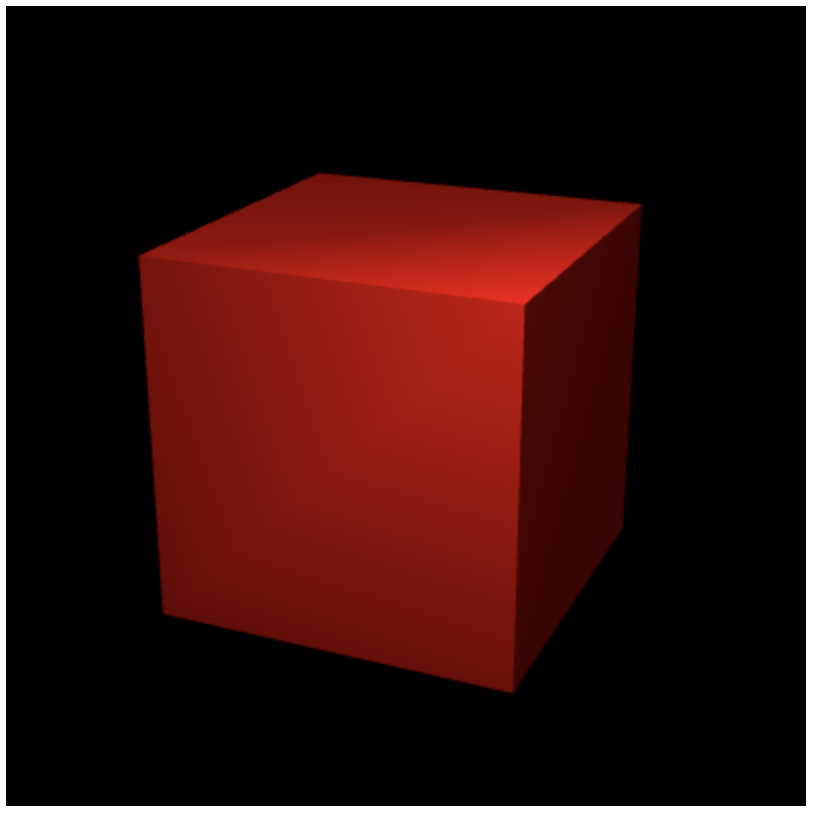
给环境光添加阴影
如上图所示,在背对光照方向的面过暗,需要额外增加环境光照才显得真实。环境反射加上漫反射组合起来的才能,两者使用加法运算,如下:
而环境反射也是用了类似方程8.2的方法:
所以,如果物体表面如果是白色(1.0, 1.0, 1.0),而环境光颜色是(0.0, 0.0, 0.2) ,则环境反射的颜色为(1.0, 1.0, 1.0)✖️(0.0, 0.0, 0.2)=(0.0, 0.0, 0.2)。
示例程序:带环境光的立方体
在前面的LightedCube_animation.js上做修改并保存为LightedCube_ambient.js。调整如下:
1、修改顶点着色器代码,使其支持环境光颜色,并将其和漫反射相加得到最终的物体颜色。
// Vertex shader program var VSHADER_SOURCE = ... 'uniform vec3 u_AmbientLight;\n' + // Color of an ambient light 'varying vec4 v_Color;\n' + 'void main() {\n' + ... // Calculate the color due to ambient reflection ' vec3 ambient = u_AmbientLight * a_Color.rgb;\n' + // Add surface colors due to diffuse and ambient reflection ' v_Color = vec4(diffuse + ambient, a_Color.a);\n' + '}\n';2. 在main()函数中,关联u_AmbientLight统一变量,并将环境光颜色(0.2, 0.2, 0.2)绑定。
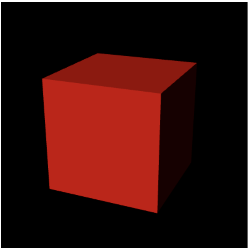
function main() { ... var u_AmbientLight = gl.getUniformLocation(gl.program, 'u_AmbientLight'); ... // Set the ambient light gl.uniform3f(u_AmbientLight, 0.2, 0.2, 0.2); ... }程序运行结果对比,左侧是没有环境光的图片,右侧为有环境光的图片。可以看到,右侧的更加明亮且背对光源的那一面效果更加真实。
照射平移-旋转对象
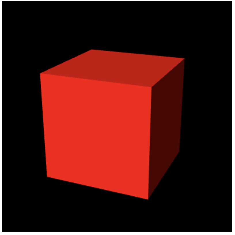
在物体进行变换时其对应的法向量也可能发生变化,如下图
逆转置矩阵
为了计算变换后物体的法向量,可通过计算原物体的模型矩阵的逆然后再转置实现。如下代码:
Matrix4 normalMatrix = new Matrix4(); // Calculate the model matrix ... // Calculate the matrix to transform normal according to the model matrix normalMatrix.setInverseOf(modelMatrix); normalMatrix.transpose();
示例程序:光照平移旋转立方体
在示例程序LightedCube_ambient.js上做修改并保存为LightedTranslatedRotatedCube.js。修改内容如下:
1. 修改顶点着色器,将法向量矩阵定义并参与计算
// Vertex shader program var VSHADER_SOURCE = ... 'uniform mat4 u_NormalMatrix;\n' + ... 'void main() {\n' + ' gl_Position = u_MvpMatrix * a_Position;\n' + // Make the length of the normal 1.0 ' vec4 normal = u_NormalMatrix * a_Normal;\n' + // Dot product of light direction and orientation of a surface ' float nDotL = max(dot(u_LightDirection, normalize(normal.xyz)), 0.0);\n' + ... '}\n';2. 在main()函数中定义模型矩阵、模型视图投影矩阵、向量矩阵。设置模型矩阵沿Y轴移动1个单位,然后绕Z轴旋转90度。最后将模型矩阵求逆转置得到法向量矩阵。
function main() { ... var vpMatrix = new Matrix4(); vpMatrix.setPerspective(32, canvas.width / canvas.height, 1, 100); vpMatrix.lookAt(3, 3, 7, 0, 0, 0, 0, 1, 0); // var currentAngle = 0.0; // Current rotation angle var modelMatrix = new Matrix4(); // Model matrix var mvpMatrix = new Matrix4(); // Model view projection matrix var normalMatrix = new Matrix4(); // Transformation matrix for normals // Calculate the model matrix modelMatrix.setTranslate(0, 1, 0); // Translate to y-axis direction; modelMatrix.rotate(90, 0, 0, 1); // Rotate around the y-axis mvpMatrix.set(vpMatrix).multiply(modelMatrix); gl.uniformMatrix4fv(u_MvpMatrix, false, mvpMatrix.elements); // Pass the matrix to transform the normal based on the normal matrix to u_NormalMatrix normalMatrix.setInverseOf(modelMatrix); normalMatrix.transpose(); gl.uniformMatrix4fv(u_NormalMatrix, false, normalMatrix.elements); ... }程序运行截图如下:
使用点光源对象
由于点光源照射到物体时,反射的光线依据表面和点光源的夹角不同而不同。所以在顶点着色器中要将点光源的位置传入。然后依据点光源与顶点坐标的位置重新计算出每个顶点的光源位置。
示例程序:点光源立方体
这里使用前面的LightedCube_ambient.js做修改并保存为PointLightedCube.js。修改内容如下。
1. 在顶点着色器中定义u_LightDirection用来接收点光源的位置,同时定义模型矩阵。
var VSHADER_SOURCE = ... 'uniform mat4 u_ModelMatrix;\n' + // Model matrix 'uniform vec3 u_LightPosition;\n' + // Position of the light source (in the world coordinate system) ... 'void main() {\n' + ... // Calculate the world coordinate of the vertex ' vec4 vertexPosition = u_ModelMatrix * a_Position;\n' + // Calculate the light direction and make it 1.0 in length ' vec3 lightDirection = normalize(u_LightPosition - vec3(vertexPosition));\n' + // Dot product of light direction and orientation of a surface ' float nDotL = max(dot(lightDirection, normalize(normal.xyz)), 0.0);\n' + ... '}\n';用vertexPosition = u_ModelMatrix * a_Position;来计算出模型顶点的世界坐标系位置。用lightDirection = normalize(u_LightPosition - vec3(vertexPosition));来计算出点光源和物体顶点在世界坐标系的差然后单位化处理得到一个光源的位置。最后将这个光源位置和法向量点乘得到光线与顶点之间的夹角cosθ。
2. 在main()中定义矩阵关联并设置光线颜色,位置,模型矩阵旋转,视点位置。
function main() { ... var u_ModelMatrix = gl.getUniformLocation(gl.program, 'u_ModelMatrix'); var u_LightColor = gl.getUniformLocation(gl.program, 'u_LightColor'); var u_LightPosition = gl.getUniformLocation(gl.program, 'u_LightPosition'); ... // Set the light color (white) gl.uniform3f(u_LightColor, 1.0, 1.0, 1.0); // Set the position of the light source (int the world coordinate) gl.uniform3f(u_LightPosition, 2.3, 4.0, 3.5); var vpMatrix = new Matrix4(); vpMatrix.setPerspective(30, canvas.width / canvas.height, 1, 100); vpMatrix.lookAt(6, 6, 14, 0, 0, 0, 0, 1, 0); var modelMatrix = new Matrix4(); // Model matrix var mvpMatrix = new Matrix4(); // Model view projection matrix var normalMatrix = new Matrix4(); // Transformation matrix for normals // Calculate the model matrix modelMatrix.setRotate(90, 0, 1, 0); // Rotate around the y-axis gl.uniformMatrix4fv(u_ModelMatrix, false, modelMatrix.elements); mvpMatrix.set(vpMatrix).multiply(modelMatrix); gl.uniformMatrix4fv(u_MvpMatrix, false, mvpMatrix.elements); ... }3. 最后修改顶点坐标initVertexBuffers(), 因为顶点都是-1,1则无法有效分辨差异,这里将顶点改成-2,2。
function initVertexBuffers(gl) { var vertices = new Float32Array([ 2.0, 2.0, 2.0, -2.0, 2.0, 2.0, -2.0,-2.0, 2.0, 2.0,-2.0, 2.0, // v0-v1-v2-v3 front 2.0, 2.0, 2.0, 2.0,-2.0, 2.0, 2.0,-2.0,-2.0, 2.0, 2.0,-2.0, // v0-v3-v4-v5 right 2.0, 2.0, 2.0, 2.0, 2.0,-2.0, -2.0, 2.0,-2.0, -2.0, 2.0, 2.0, // v0-v5-v6-v1 up -2.0, 2.0, 2.0, -2.0, 2.0,-2.0, -2.0,-2.0,-2.0, -2.0,-2.0, 2.0, // v1-v6-v7-v2 left -2.0,-2.0,-2.0, 2.0,-2.0,-2.0, 2.0,-2.0, 2.0, -2.0,-2.0, 2.0, // v7-v4-v3-v2 down 2.0,-2.0,-2.0, -2.0,-2.0,-2.0, -2.0, 2.0,-2.0, 2.0, 2.0,-2.0 // v4-v7-v6-v5 back ]); ... }运行结果如下图:
让点光源的立方体旋转
1. 在main()函数中增加tick,并调用动画请求
var tick = function() { currentAngle = animate(currentAngle); // Update the rotation angle // Calculate the model matrix modelMatrix.setRotate(currentAngle, 0, 1, 0); // Rotate around the y-axis gl.uniformMatrix4fv(u_ModelMatrix, false, modelMatrix.elements); mvpMatrix.set(vpMatrix).multiply(modelMatrix); gl.uniformMatrix4fv(u_MvpMatrix, false, mvpMatrix.elements); // Pass the matrix to transform the normal based on the normal matrix to u_NormalMatrix normalMatrix.setInverseOf(modelMatrix); normalMatrix.transpose(); gl.uniformMatrix4fv(u_NormalMatrix, false, normalMatrix.elements); // Clear color and depth buffer gl.clear(gl.COLOR_BUFFER_BIT | gl.DEPTH_BUFFER_BIT); // Draw the cube gl.drawElements(gl.TRIANGLES, n, gl.UNSIGNED_BYTE, 0); requestAnimationFrame(tick, canvas); // Request that the browser calls tick } tick();2. 依据逝时间获取旋转的角度,每秒旋转30度。
// Rotation angle (degree/second) var ANGLE_STEP = 30.0; // Last time when this function was called var g_last = Date.now(); function animate(angle) { // Calculate the elapsed time var now = Date.now(); var elapsed = now - g_last; // milliseconds g_last = now; // Update the current rotation angle (adjusted by the elapsed time) var newAngle = angle + (ANGLE_STEP * elapsed) / 1000.0; return newAngle %= 360; }运行结果同上,差异是绕y轴旋转。
不带片段差值和带片段差值的两个球体
不带片段差值的球体:
将点光源程序PointLightedCube.js做修改,并保存PointLighteSphere.js,做下列修改
1. 重写initVertexBuffer()函数,使其绘制球体,并同时设置球体的法向量、索引表、颜色。
function initVertexBuffers(gl) { var SPHERE_DIV = 13; var i, ai, si, ci; var j, aj, sj, cj; var p1, p2; var positions = []; var indices = []; // Generate coordinates for (j = 0; j the negative rotation of joint1 around the z-axis if (g_joint1Angle > -135.0) g_joint1Angle -= ANGLE_STEP; break; case 39: // Right arrow key -> the positive rotation of arm1 around the y-axis g_arm1Angle = (g_arm1Angle + ANGLE_STEP) % 360; break; case 37: // Left arrow key -> the negative rotation of arm1 around the y-axis g_arm1Angle = (g_arm1Angle - ANGLE_STEP) % 360; break; default: return; // Skip drawing at no effective action } // Draw the robot arm draw(gl, n, viewProjMatrix, u_MvpMatrix, u_NormalMatrix); }5. 初始化顶点缓冲区
将长方体原点设置在底面中心位置,以便后续操作方便。然后定义法向量和索引表,定义表面颜色,最后绑定索引表。
function initVertexBuffers(gl) { // Vertex coordinates(a cuboid 3.0 in width, 10.0 in height, and 3.0 in length with its origin at the center of its bottom) var vertices = new Float32Array([ 1.5, 10.0, 1.5, -1.5, 10.0, 1.5, -1.5, 0.0, 1.5, 1.5, 0.0, 1.5, // v0-v1-v2-v3 front 1.5, 10.0, 1.5, 1.5, 0.0, 1.5, 1.5, 0.0,-1.5, 1.5, 10.0,-1.5, // v0-v3-v4-v5 right 1.5, 10.0, 1.5, 1.5, 10.0,-1.5, -1.5, 10.0,-1.5, -1.5, 10.0, 1.5, // v0-v5-v6-v1 up -1.5, 10.0, 1.5, -1.5, 10.0,-1.5, -1.5, 0.0,-1.5, -1.5, 0.0, 1.5, // v1-v6-v7-v2 left -1.5, 0.0,-1.5, 1.5, 0.0,-1.5, 1.5, 0.0, 1.5, -1.5, 0.0, 1.5, // v7-v4-v3-v2 down 1.5, 0.0,-1.5, -1.5, 0.0,-1.5, -1.5, 10.0,-1.5, 1.5, 10.0,-1.5 // v4-v7-v6-v5 back ]); // Normal var normals = new Float32Array([ 0.0, 0.0, 1.0, 0.0, 0.0, 1.0, 0.0, 0.0, 1.0, 0.0, 0.0, 1.0, // v0-v1-v2-v3 front 1.0, 0.0, 0.0, 1.0, 0.0, 0.0, 1.0, 0.0, 0.0, 1.0, 0.0, 0.0, // v0-v3-v4-v5 right 0.0, 1.0, 0.0, 0.0, 1.0, 0.0, 0.0, 1.0, 0.0, 0.0, 1.0, 0.0, // v0-v5-v6-v1 up -1.0, 0.0, 0.0, -1.0, 0.0, 0.0, -1.0, 0.0, 0.0, -1.0, 0.0, 0.0, // v1-v6-v7-v2 left 0.0,-1.0, 0.0, 0.0,-1.0, 0.0, 0.0,-1.0, 0.0, 0.0,-1.0, 0.0, // v7-v4-v3-v2 down 0.0, 0.0,-1.0, 0.0, 0.0,-1.0, 0.0, 0.0,-1.0, 0.0, 0.0,-1.0 // v4-v7-v6-v5 back ]); // Indices of the vertices var indices = new Uint8Array([ 0, 1, 2, 0, 2, 3, // front 4, 5, 6, 4, 6, 7, // right 8, 9,10, 8,10,11, // up 12,13,14, 12,14,15, // left 16,17,18, 16,18,19, // down 20,21,22, 20,22,23 // back ]); // Unbind the buffer object gl.bindBuffer(gl.ARRAY_BUFFER, null); // Create a buffer object var indexBuffer = gl.createBuffer(); if (!indexBuffer) { console.log('Failed to create the buffer object'); return -1; } // Write the vertex coordinates,normal,color to the buffer object if (!initArrayBuffer(gl, 'a_Position', vertices, 3, gl.FLOAT)) return -1; if (!initArrayBuffer(gl, 'a_Normal', normals, 3, gl.FLOAT)) return -1; var a_Color = gl.getAttribLocation(gl.program, 'a_Color'); gl.vertexAttrib4f(a_Color, 1.0, 0.4, 0.0, 1.0); // Write the indices to the buffer object gl.bindBuffer(gl.ELEMENT_ARRAY_BUFFER, indexBuffer); gl.bufferData(gl.ELEMENT_ARRAY_BUFFER, indices, gl.STATIC_DRAW); return indices.length; }6. 绘制函数draw()
定义全局变量g_modelMatrix, g_mvpMatrix。在draw()中,设置臂1下移-12个单位,然后绕Y轴旋转g_arm1Angle角度,其值来自按键事件触发,绘制臂1。
臂2先上移到臂1的高度,使其“链接”然后绕Z轴旋转g_joint1Angle角度,其值来自按键事件触发,x方向和z方向放大1.3倍以示区别。最后绘制图像。
注意,这里使用全局变量g_modelMatrix先设置了臂1,然后在此基础上设置臂2,这样就能实现臂1绕Y轴旋转也能使臂2绕Y轴旋转。而当旋转臂2时臂1还是从setTranslate开始且g_arm1Angle保持上一次的,所以能够做到臂2旋转而臂1不旋转。
// Coordinate transformation matrix var g_modelMatrix = new Matrix4(), g_mvpMatrix = new Matrix4(); function draw(gl, n, viewProjMatrix, u_MvpMatrix, u_NormalMatrix) { // Clear color and depth buffer gl.clear(gl.COLOR_BUFFER_BIT | gl.DEPTH_BUFFER_BIT); // Arm1 var arm1Length = 10.0; // Length of arm1 g_modelMatrix.setTranslate(0.0, -12.0, 0.0); g_modelMatrix.rotate(g_arm1Angle, 0.0, 1.0, 0.0); // Rotate around the y-axis drawBox(gl, n, viewProjMatrix, u_MvpMatrix, u_NormalMatrix); // Draw // Arm2 g_modelMatrix.translate(0.0, arm1Length, 0.0); // Move to joint1 g_modelMatrix.rotate(g_joint1Angle, 0.0, 0.0, 1.0); // Rotate around the z-axis g_modelMatrix.scale(1.3, 1.0, 1.3); // Make it a little thicker drawBox(gl, n, viewProjMatrix, u_MvpMatrix, u_NormalMatrix); // Draw }7. 绘制立方体drawBox()
定义一个全局的法向量矩阵g_normalMatrix。 全局的模型视图矩阵初始化为视图矩阵,然后乘上全局的模型矩阵并将结果送入顶点着色器。接着计算法向量,先求全局矩阵的逆再转置,最后也送入顶点着色器。完毕后,调用三角形绘图。
var g_normalMatrix = new Matrix4(); // Coordinate transformation matrix for normals // Draw the cube function drawBox(gl, n, viewProjMatrix, u_MvpMatrix, u_NormalMatrix) { // Calculate the model view project matrix and pass it to u_MvpMatrix g_mvpMatrix.set(viewProjMatrix); g_mvpMatrix.multiply(g_modelMatrix); gl.uniformMatrix4fv(u_MvpMatrix, false, g_mvpMatrix.elements); // Calculate the normal transformation matrix and pass it to u_NormalMatrix g_normalMatrix.setInverseOf(g_modelMatrix); g_normalMatrix.transpose(); gl.uniformMatrix4fv(u_NormalMatrix, false, g_normalMatrix.elements); // Draw gl.drawElements(gl.TRIANGLES, n, gl.UNSIGNED_BYTE, 0); }运行结果:
按方向的左右键,臂1(下方)绕Y轴旋转,同时臂2(上方)也会跟着旋转。按上下键,则臂1不动,臂2绕Z轴旋转。
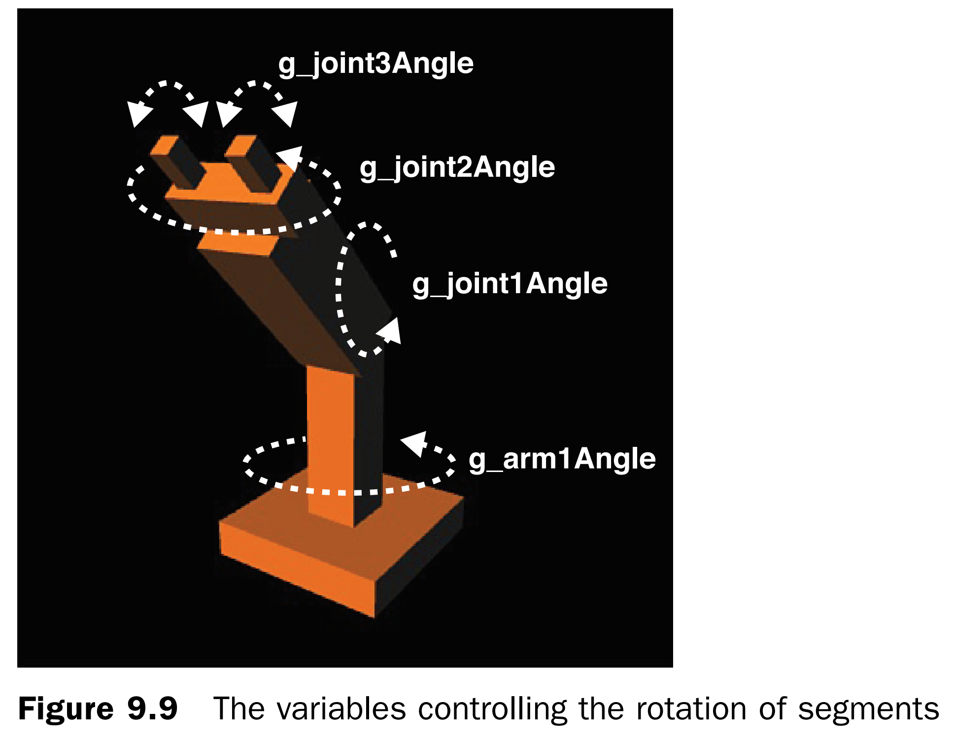
多关节模型示例程序
在单关节示例基础上,扩展多关节模型,增加手腕和手指。其中手腕绕Y轴旋转,手指绕X轴旋转。
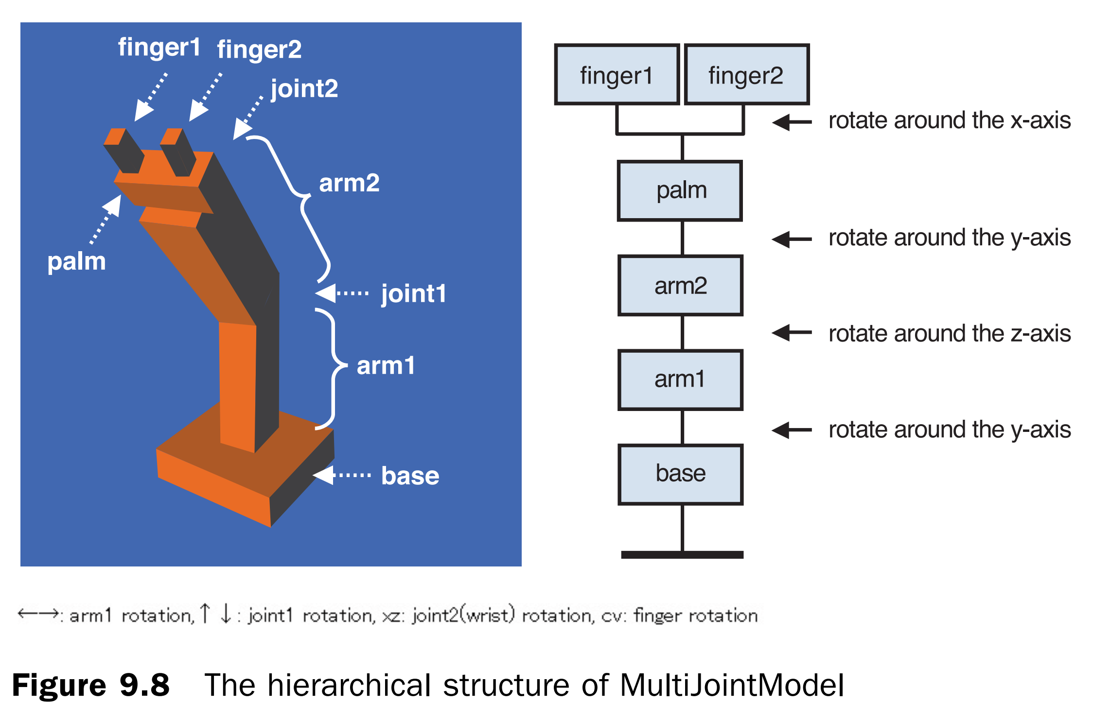
1. 按键事件修改,支持z,x使手腕旋转,支持v,c使手指旋转。
var ANGLE_STEP = 3.0; // The increments of rotation angle (degrees) var g_arm1Angle = 90.0; // The rotation angle of arm1 (degrees) var g_joint1Angle = 45.0; // The rotation angle of joint1 (degrees) var g_joint2Angle = 0.0; // The rotation angle of joint2 (degrees) var g_joint3Angle = 0.0; // The rotation angle of joint3 (degrees) function keydown(ev, gl, n, viewProjMatrix, u_MvpMatrix, u_NormalMatrix) { switch (ev.keyCode) { case 40: // Up arrow key -> the positive rotation of joint1 around the z-axis if (g_joint1Angle the negative rotation of joint1 around the z-axis if (g_joint1Angle > -135.0) g_joint1Angle -= ANGLE_STEP; break; case 39: // Right arrow key -> the positive rotation of arm1 around the y-axis g_arm1Angle = (g_arm1Angle + ANGLE_STEP) % 360; break; case 37: // Left arrow key -> the negative rotation of arm1 around the y-axis g_arm1Angle = (g_arm1Angle - ANGLE_STEP) % 360; break; case 90: // 'z'key -> the positive rotation of joint2 g_joint2Angle = (g_joint2Angle + ANGLE_STEP) % 360; break; case 88: // 'x'key -> the negative rotation of joint2 g_joint2Angle = (g_joint2Angle - ANGLE_STEP) % 360; break; case 86: // 'v'key -> the positive rotation of joint3 if (g_joint3Angle the nagative rotation of joint3 if (g_joint3Angle > -60.0) g_joint3Angle = (g_joint3Angle - ANGLE_STEP) % 360; break; default: return; // Skip drawing at no effective action } // Draw the robot arm draw(gl, n, viewProjMatrix, u_MvpMatrix, u_NormalMatrix); }2. 修改initVertexBuffers()函数,初始化顶点坐标位置
function initVertexBuffers(gl) { var vertices = new Float32Array([ 0.5, 1.0, 0.5, -0.5, 1.0, 0.5, -0.5, 0.0, 0.5, 0.5, 0.0, 0.5, // v0-v1-v2-v3 front 0.5, 1.0, 0.5, 0.5, 0.0, 0.5, 0.5, 0.0,-0.5, 0.5, 1.0,-0.5, // v0-v3-v4-v5 right 0.5, 1.0, 0.5, 0.5, 1.0,-0.5, -0.5, 1.0,-0.5, -0.5, 1.0, 0.5, // v0-v5-v6-v1 up -0.5, 1.0, 0.5, -0.5, 1.0,-0.5, -0.5, 0.0,-0.5, -0.5, 0.0, 0.5, // v1-v6-v7-v2 left -0.5, 0.0,-0.5, 0.5, 0.0,-0.5, 0.5, 0.0, 0.5, -0.5, 0.0, 0.5, // v7-v4-v3-v2 down 0.5, 0.0,-0.5, -0.5, 0.0,-0.5, -0.5, 1.0,-0.5, 0.5, 1.0,-0.5 // v4-v7-v6-v5 back ]); ... }3. 修改draw()函数
增加基台、手腕和两个手指,其中基台是首先创建的。
// Coordinate transformation matrix var g_modelMatrix = new Matrix4(), g_mvpMatrix = new Matrix4(); function draw(gl, n, viewProjMatrix, u_MvpMatrix, u_NormalMatrix) { // Clear color and depth buffer gl.clear(gl.COLOR_BUFFER_BIT | gl.DEPTH_BUFFER_BIT); // Draw a base var baseHeight = 2.0; g_modelMatrix.setTranslate(0.0, -12.0, 0.0); drawBox(gl, n, 10.0, baseHeight, 10.0, viewProjMatrix, u_MvpMatrix, u_NormalMatrix); // Arm1 var arm1Length = 10.0; g_modelMatrix.translate(0.0, baseHeight, 0.0); // Move onto the base g_modelMatrix.rotate(g_arm1Angle, 0.0, 1.0, 0.0); // Rotate around the y-axis drawBox(gl, n, 3.0, arm1Length, 3.0, viewProjMatrix, u_MvpMatrix, u_NormalMatrix); // Draw // Arm2 var arm2Length = 10.0; g_modelMatrix.translate(0.0, arm1Length, 0.0); // Move to joint1 g_modelMatrix.rotate(g_joint1Angle, 0.0, 0.0, 1.0); // Rotate around the z-axis drawBox(gl, n, 4.0, arm2Length, 4.0, viewProjMatrix, u_MvpMatrix, u_NormalMatrix); // Draw // A palm var palmLength = 2.0; g_modelMatrix.translate(0.0, arm2Length, 0.0); // Move to palm g_modelMatrix.rotate(g_joint2Angle, 0.0, 1.0, 0.0); // Rotate around the y-axis drawBox(gl, n, 2.0, palmLength, 6.0, viewProjMatrix, u_MvpMatrix, u_NormalMatrix); // Draw // Move to the center of the tip of the palm g_modelMatrix.translate(0.0, palmLength, 0.0); // Draw finger1 pushMatrix(g_modelMatrix); g_modelMatrix.translate(0.0, 0.0, 2.0); g_modelMatrix.rotate(g_joint3Angle, 1.0, 0.0, 0.0); // Rotate around the x-axis drawBox(gl, n, 1.0, 2.0, 1.0, viewProjMatrix, u_MvpMatrix, u_NormalMatrix); g_modelMatrix = popMatrix(); // Draw finger2 g_modelMatrix.translate(0.0, 0.0, -2.0); g_modelMatrix.rotate(-g_joint3Angle, 1.0, 0.0, 0.0); // Rotate around the x-axis drawBox(gl, n, 1.0, 2.0, 1.0, viewProjMatrix, u_MvpMatrix, u_NormalMatrix); }由于手指1和手指2是同级别即兄弟关系,所以必须把g_modelMatrix压入堆栈里,等绘制手指1后再弹出堆栈继续绘制手指2。否则的话,如果不压入堆栈,手指2是直接在手指1绘制结束的位置继续绘制手指2。
4. 压入堆栈和弹出堆栈
这里使用了全局变量g_matrixStack。
var g_matrixStack = []; // Array for storing a matrix function pushMatrix(m) { // Store the specified matrix to the array var m2 = new Matrix4(m); g_matrixStack.push(m2); } function popMatrix() { // Retrieve the matrix from the array return g_matrixStack.pop(); }5. 绘制立方体函数drawBox()修改
这里修改了参数,第3到第5个参数为长方体的宽度、高度、深度。
var g_normalMatrix = new Matrix4(); // Coordinate transformation matrix for normals // Draw the cube function drawBox(gl, n, width, height, depth, viewProjMatrix, u_MvpMatrix, u_NormalMatrix) { pushMatrix(g_modelMatrix); // Save the model matrix // Scale a cube and draw g_modelMatrix.scale(width, height, depth); ... g_modelMatrix = popMatrix(); // Retrieve the model matrix }在绘制之前,将当前的模型矩阵压入堆栈,然后缩放和绘制图形,完毕后将压入堆栈中的模型矩阵恢复。
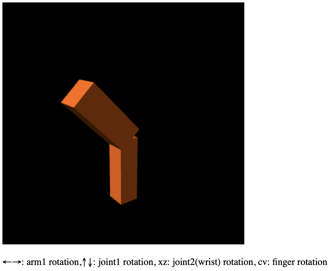
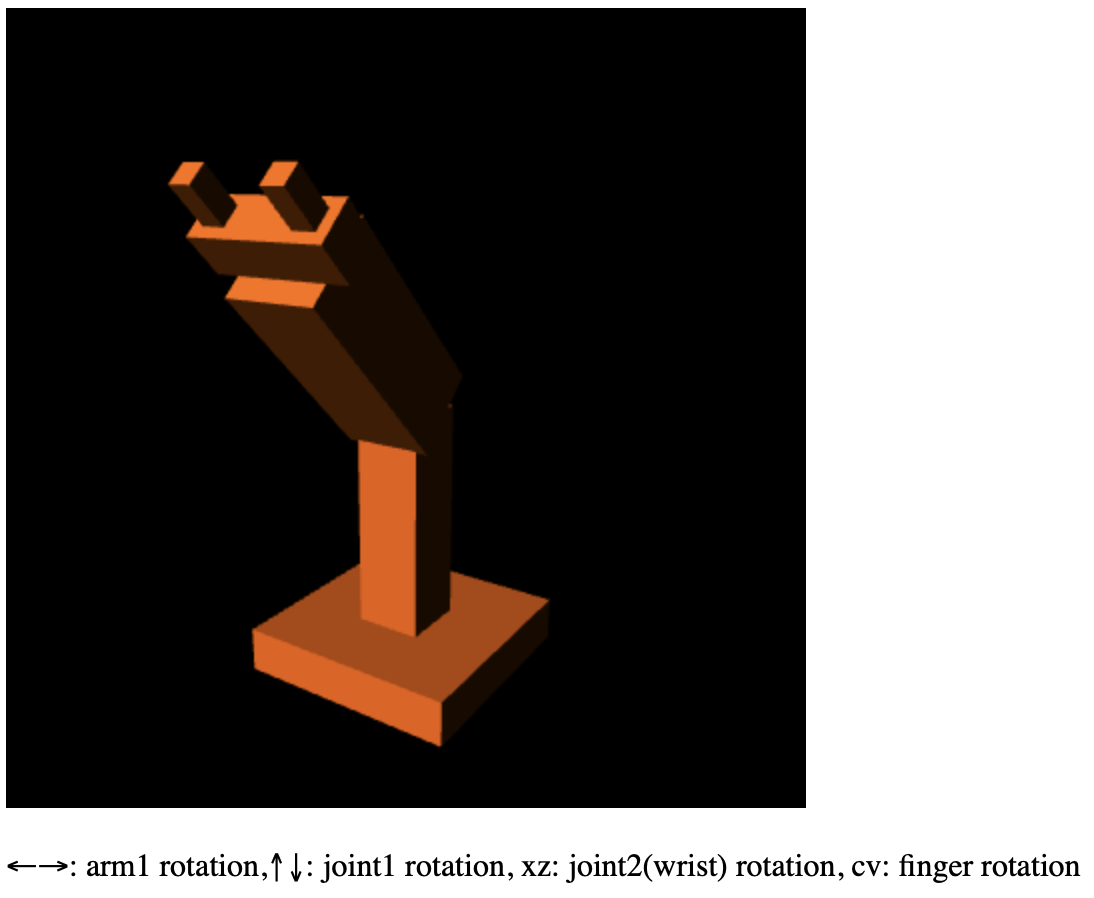
运行结果截图:
分段模型实现多关节模型示例程序
在上面的例子中,使用了单个模型顶点坐标,通过变换的方法来实现底座、臂1、臂2、手掌、2个手指。在本例中,则每个模型各自独立即采用分段模型的方法。好在都是使用的长方体,所以法向量及顶点索引维持一致无需改变。
在MultiJointModel.js上做修改,并另存为MultiJointModel_segment.js。修改内容如下:
1. 初始化顶点缓冲区initVertexBuffers()函数修改
由于这次采用分段编写,每个模型顶点个字独立,需要编写个字的顶点坐标。同时创建了5哥全局缓冲区变量,用来存储5个模型的缓冲区以便在draw()和initVertexBuffers()中使用。最后使用initArrayBufferForLaterUse()函数来初始化这5个缓冲区。其余部分维持不变。
var g_baseBuffer = null; // Buffer object for a base var g_arm1Buffer = null; // Buffer object for arm1 var g_arm2Buffer = null; // Buffer object for arm2 var g_palmBuffer = null; // Buffer object for a palm var g_fingerBuffer = null; // Buffer object for fingers function initVertexBuffers(gl) { // Vertex coordinate (prepare coordinates of cuboids for all segments) var vertices_base = new Float32Array([ // Base(10x2x10) 5.0, 2.0, 5.0, -5.0, 2.0, 5.0, -5.0, 0.0, 5.0, 5.0, 0.0, 5.0, // v0-v1-v2-v3 front 5.0, 2.0, 5.0, 5.0, 0.0, 5.0, 5.0, 0.0,-5.0, 5.0, 2.0,-5.0, // v0-v3-v4-v5 right 5.0, 2.0, 5.0, 5.0, 2.0,-5.0, -5.0, 2.0,-5.0, -5.0, 2.0, 5.0, // v0-v5-v6-v1 up -5.0, 2.0, 5.0, -5.0, 2.0,-5.0, -5.0, 0.0,-5.0, -5.0, 0.0, 5.0, // v1-v6-v7-v2 left -5.0, 0.0,-5.0, 5.0, 0.0,-5.0, 5.0, 0.0, 5.0, -5.0, 0.0, 5.0, // v7-v4-v3-v2 down 5.0, 0.0,-5.0, -5.0, 0.0,-5.0, -5.0, 2.0,-5.0, 5.0, 2.0,-5.0 // v4-v7-v6-v5 back ]); var vertices_arm1 = new Float32Array([ // Arm1(3x10x3) 1.5, 10.0, 1.5, -1.5, 10.0, 1.5, -1.5, 0.0, 1.5, 1.5, 0.0, 1.5, // v0-v1-v2-v3 front 1.5, 10.0, 1.5, 1.5, 0.0, 1.5, 1.5, 0.0,-1.5, 1.5, 10.0,-1.5, // v0-v3-v4-v5 right 1.5, 10.0, 1.5, 1.5, 10.0,-1.5, -1.5, 10.0,-1.5, -1.5, 10.0, 1.5, // v0-v5-v6-v1 up -1.5, 10.0, 1.5, -1.5, 10.0,-1.5, -1.5, 0.0,-1.5, -1.5, 0.0, 1.5, // v1-v6-v7-v2 left -1.5, 0.0,-1.5, 1.5, 0.0,-1.5, 1.5, 0.0, 1.5, -1.5, 0.0, 1.5, // v7-v4-v3-v2 down 1.5, 0.0,-1.5, -1.5, 0.0,-1.5, -1.5, 10.0,-1.5, 1.5, 10.0,-1.5 // v4-v7-v6-v5 back ]); var vertices_arm2 = new Float32Array([ // Arm2(4x10x4) 2.0, 10.0, 2.0, -2.0, 10.0, 2.0, -2.0, 0.0, 2.0, 2.0, 0.0, 2.0, // v0-v1-v2-v3 front 2.0, 10.0, 2.0, 2.0, 0.0, 2.0, 2.0, 0.0,-2.0, 2.0, 10.0,-2.0, // v0-v3-v4-v5 right 2.0, 10.0, 2.0, 2.0, 10.0,-2.0, -2.0, 10.0,-2.0, -2.0, 10.0, 2.0, // v0-v5-v6-v1 up -2.0, 10.0, 2.0, -2.0, 10.0,-2.0, -2.0, 0.0,-2.0, -2.0, 0.0, 2.0, // v1-v6-v7-v2 left -2.0, 0.0,-2.0, 2.0, 0.0,-2.0, 2.0, 0.0, 2.0, -2.0, 0.0, 2.0, // v7-v4-v3-v2 down 2.0, 0.0,-2.0, -2.0, 0.0,-2.0, -2.0, 10.0,-2.0, 2.0, 10.0,-2.0 // v4-v7-v6-v5 back ]); var vertices_palm = new Float32Array([ // Palm(2x2x6) 1.0, 2.0, 3.0, -1.0, 2.0, 3.0, -1.0, 0.0, 3.0, 1.0, 0.0, 3.0, // v0-v1-v2-v3 front 1.0, 2.0, 3.0, 1.0, 0.0, 3.0, 1.0, 0.0,-3.0, 1.0, 2.0,-3.0, // v0-v3-v4-v5 right 1.0, 2.0, 3.0, 1.0, 2.0,-3.0, -1.0, 2.0,-3.0, -1.0, 2.0, 3.0, // v0-v5-v6-v1 up -1.0, 2.0, 3.0, -1.0, 2.0,-3.0, -1.0, 0.0,-3.0, -1.0, 0.0, 3.0, // v1-v6-v7-v2 left -1.0, 0.0,-3.0, 1.0, 0.0,-3.0, 1.0, 0.0, 3.0, -1.0, 0.0, 3.0, // v7-v4-v3-v2 down 1.0, 0.0,-3.0, -1.0, 0.0,-3.0, -1.0, 2.0,-3.0, 1.0, 2.0,-3.0 // v4-v7-v6-v5 back ]); var vertices_finger = new Float32Array([ // Fingers(1x2x1) 0.5, 2.0, 0.5, -0.5, 2.0, 0.5, -0.5, 0.0, 0.5, 0.5, 0.0, 0.5, // v0-v1-v2-v3 front 0.5, 2.0, 0.5, 0.5, 0.0, 0.5, 0.5, 0.0,-0.5, 0.5, 2.0,-0.5, // v0-v3-v4-v5 right 0.5, 2.0, 0.5, 0.5, 2.0,-0.5, -0.5, 2.0,-0.5, -0.5, 2.0, 0.5, // v0-v5-v6-v1 up -0.5, 2.0, 0.5, -0.5, 2.0,-0.5, -0.5, 0.0,-0.5, -0.5, 0.0, 0.5, // v1-v6-v7-v2 left -0.5, 0.0,-0.5, 0.5, 0.0,-0.5, 0.5, 0.0, 0.5, -0.5, 0.0, 0.5, // v7-v4-v3-v2 down 0.5, 0.0,-0.5, -0.5, 0.0,-0.5, -0.5, 2.0,-0.5, 0.5, 2.0,-0.5 // v4-v7-v6-v5 back ]); ... // Write coords to buffers, but don't assign to attribute variables g_baseBuffer = initArrayBufferForLaterUse(gl, vertices_base, 3, gl.FLOAT); g_arm1Buffer = initArrayBufferForLaterUse(gl, vertices_arm1, 3, gl.FLOAT); g_arm2Buffer = initArrayBufferForLaterUse(gl, vertices_arm2, 3, gl.FLOAT); g_palmBuffer = initArrayBufferForLaterUse(gl, vertices_palm, 3, gl.FLOAT); g_fingerBuffer = initArrayBufferForLaterUse(gl, vertices_finger, 3, gl.FLOAT); if (!g_baseBuffer || !g_arm1Buffer || !g_arm2Buffer || !g_palmBuffer || !g_fingerBuffer) return -1; ... }2. 新定义了一个函数initArrayBufferForLaterUse()用来初始化5个模型的绑定,并使用对象属性的方式给buffer对象添加了num和type属性,并返回。
function initArrayBufferForLaterUse(gl, data, num, type) { var buffer = gl.createBuffer(); // Create a buffer object if ((!buffer)) { console.log('Failed to create the buffer object'); return false; } // Write the vertex coordinates and color to the buffer object gl.bindBuffer(gl.ARRAY_BUFFER, buffer); gl.bufferData(gl.ARRAY_BUFFER, data, gl.STATIC_DRAW); // Store information to assign it to attribute variable later buffer.num = num; buffer.type = type; return buffer; }3. 修改main()函数,将顶点着色器中的a_Position的属性变量关联到main()函数中,设置按键事件和draw()函数增加顶点参数a_Position。
function main() { ... // Set the vertex coordinates and color (blue triangle is in front) var n = initVertexBuffers(gl); if (n4. 修改按键事件,a_Position传递给draw()
function keydown(ev, gl, n, a_Position, viewProjMatrix, u_MvpMatrix, u_NormalMatrix) { ... // Draw the robot arm draw(gl, n, a_Position, viewProjMatrix, u_MvpMatrix, u_NormalMatrix); }5. 修改draw()函数,将每个模型分别绘制,具体绘制使用drawSegment()来实现,注意,两个手指的绘制依旧使用postMatrix()和popMatrix来保存和恢复场景。这里由于使用了具体每个模型的顶点,所以删除了缩放代码。
function draw(gl, n, a_Position, viewProjMatrix, u_MvpMatrix, u_NormalMatrix) { // Clear color and depth buffer gl.clear(gl.COLOR_BUFFER_BIT | gl.DEPTH_BUFFER_BIT); // Draw a base var baseHeight = 2.0; g_modelMatrix.setTranslate(0.0, -12.0, 0.0); drawSegment(gl, n, g_baseBuffer, a_Position, viewProjMatrix, u_MvpMatrix, u_NormalMatrix); // Arm1 var arm1Length = 10.0; g_modelMatrix.translate(0.0, baseHeight, 0.0); // Move to the tip of the base g_modelMatrix.rotate(g_arm1Angle, 0.0, 1.0, 0.0); // Rotate around the y-axis drawSegment(gl, n, g_arm1Buffer, a_Position, viewProjMatrix, u_MvpMatrix, u_NormalMatrix); // Draw // Arm2 var arm2Length = 10.0; g_modelMatrix.translate(0.0, arm1Length, 0.0); // Move to joint1 g_modelMatrix.rotate(g_joint1Angle, 0.0, 0.0, 1.0); // Rotate around the z-axis drawSegment(gl, n, g_arm2Buffer, a_Position, viewProjMatrix, u_MvpMatrix, u_NormalMatrix); // Draw // A palm var palmLength = 2.0; g_modelMatrix.translate(0.0, arm2Length, 0.0); // Move to palm g_modelMatrix.rotate(g_joint2Angle, 0.0, 1.0, 0.0); // Rotate around the y-axis drawSegment(gl, n, g_palmBuffer, a_Position, viewProjMatrix, u_MvpMatrix, u_NormalMatrix); // Draw // Move to the center of the tip of the palm g_modelMatrix.translate(0.0, palmLength, 0.0); // Draw finger1 pushMatrix(g_modelMatrix); g_modelMatrix.translate(0.0, 0.0, 2.0); g_modelMatrix.rotate(g_joint3Angle, 1.0, 0.0, 0.0); // Rotate around the x-axis drawSegment(gl, n, g_fingerBuffer, a_Position, viewProjMatrix, u_MvpMatrix, u_NormalMatrix); g_modelMatrix = popMatrix(); // Draw finger2 g_modelMatrix.translate(0.0, 0.0, -2.0); g_modelMatrix.rotate(-g_joint3Angle, 1.0, 0.0, 0.0); // Rotate around the x-axis drawSegment(gl, n, g_fingerBuffer, a_Position, viewProjMatrix, u_MvpMatrix, u_NormalMatrix); }6. 修改drawSegment函数,增加了buffer, a_Position两个参数,删除了尺寸参数。另外,由于drawSegment是在真正绘制前发生的,所以需要将模型缓冲区绑定到a_Position,并开启允许缓冲区。
var g_normalMatrix = new Matrix4(); // Coordinate transformation matrix for normals // Draw the cube function drawSegment(gl, n, buffer, a_Position, viewProjMatrix, u_MvpMatrix, u_NormalMatrix) { gl.bindBuffer(gl.ARRAY_BUFFER, buffer); // Assign the buffer object to the attribute variable gl.vertexAttribPointer(a_Position, buffer.num, buffer.type, false, 0, 0); // Enable the assignment gl.enableVertexAttribArray(a_Position); ... }运行结果同MultiJointModel.js,效果相同,只是不同的实现理念。截图略。